
Shock wave modification method and system

a technology of shock wave and fluid, applied in the field of facilitating movement, can solve the problems of undesirable augmentation of acoustic signature, reduce the efficiency of the desired momentum transfer from the vehicle to the effluent stream, and undesirable effects, so as to reduce the pressure behind the shock wave, reduce the density, and reduce the effect of pressur

Inactive Publication Date: 2010-01-19
KREMEYER KEVIN
View PDF9 Cites 25 Cited by
  • Summary
  • Abstract
  • Description
  • Claims
  • Application Information

AI Technical Summary

Benefits of technology

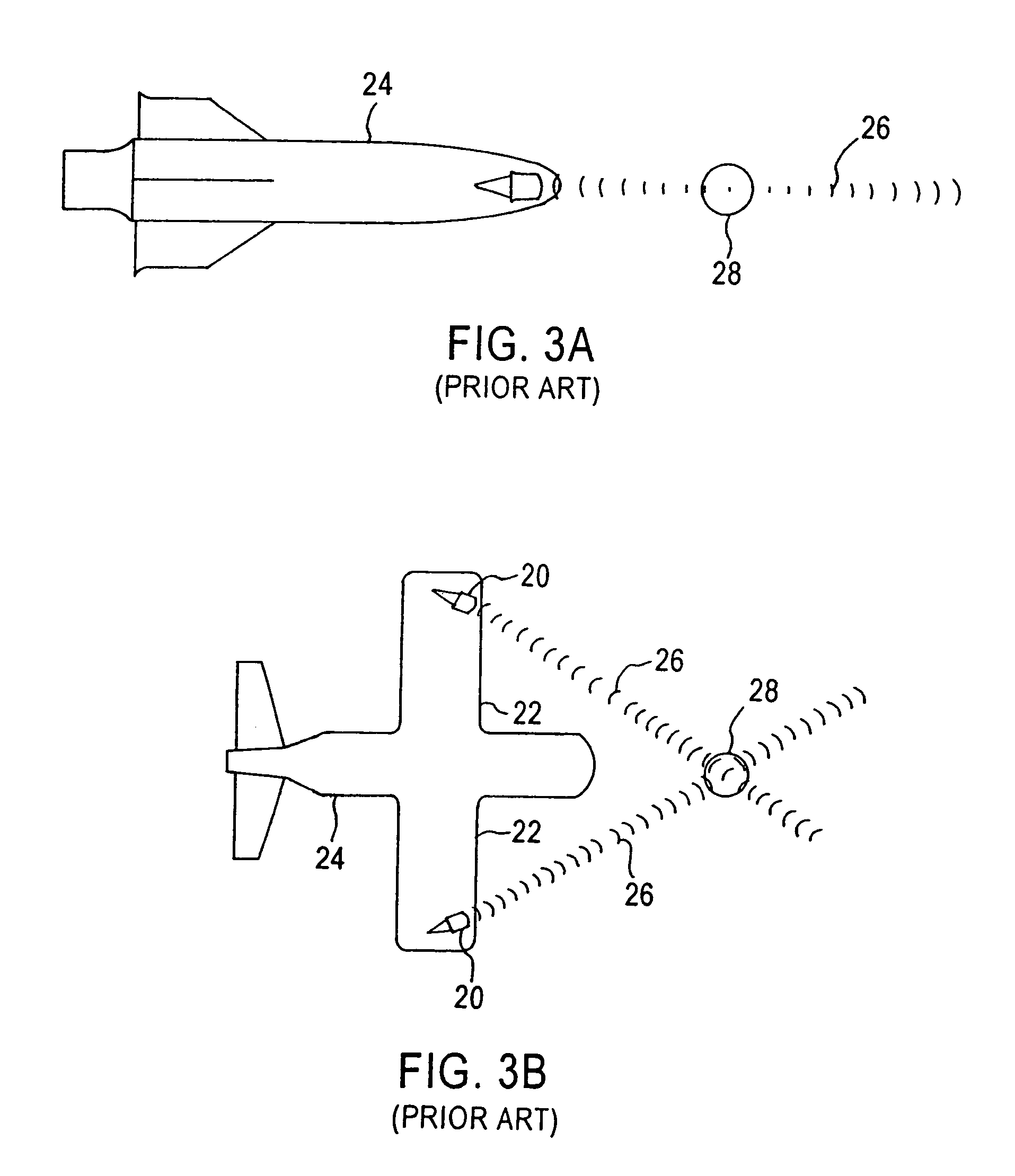
"The present invention provides a system and method for transferring information to and from a body through a fluid. The system includes a means for heating the fluid along a path to form a volume of heated fluid expanding outwardly from the path. A line of ionized fluid is formed by the means for heating the fluid along the path, which functions as an antenna for transferring the information. The system can modify the effects of a shock wave formed in the fluid by heating the fluid along the path and transferring the information to or from the body at a timed relative to the heating. The information can be transmitted from the body and received by the body after passing through the shock wave via the volume of heated fluid. The means for heating the fluid can include a filamenting laser, electric current, or microwaves. The information can include electromagnetic waves or acoustic waves. The system can also include antennae extending through the shock wave. The invention has advantages in transferring information through a fluid and modifying the effects of a shock wave on the information."

Problems solved by technology

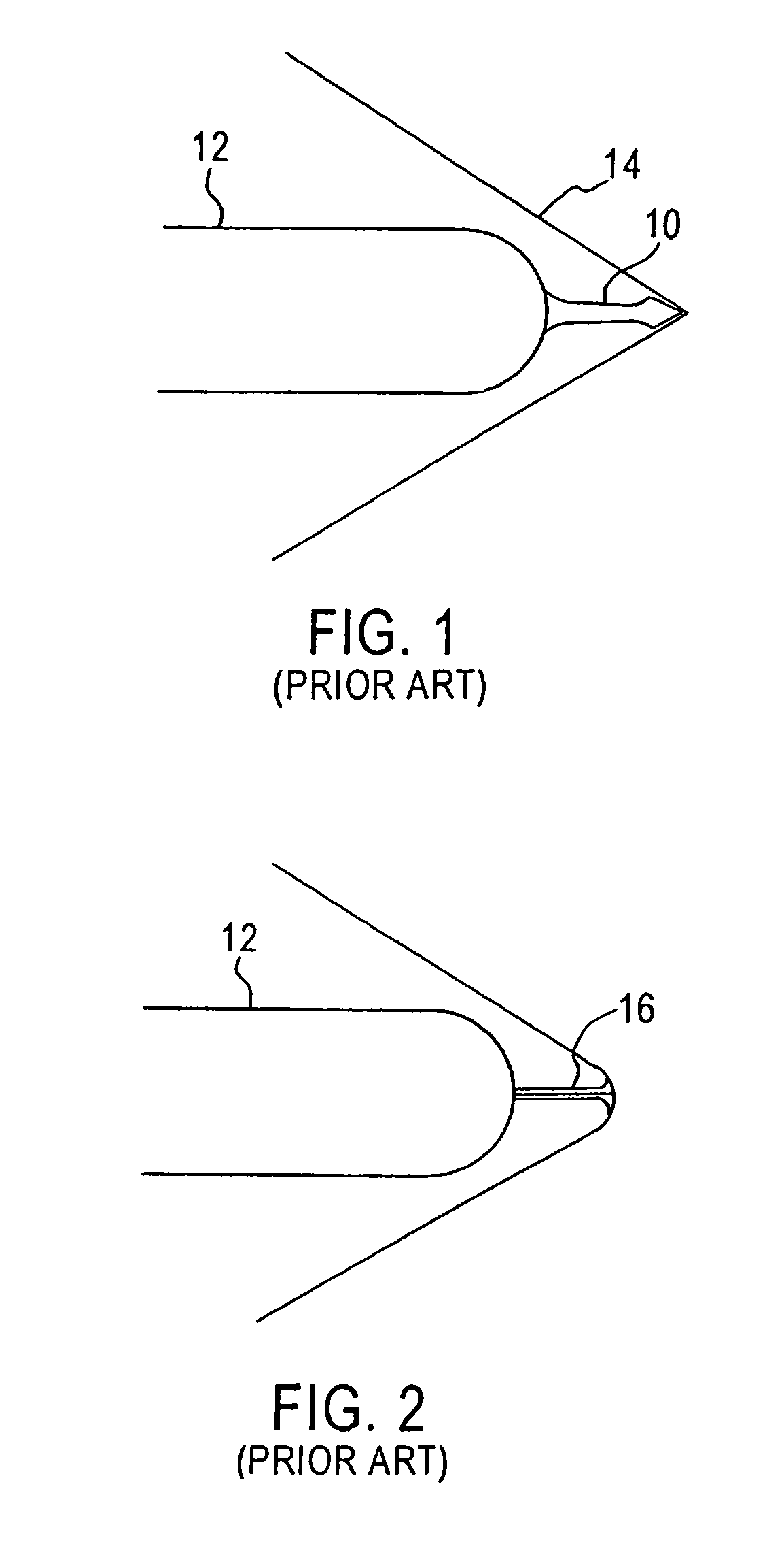
When a shock wave is formed in a supersonic stream of a fluid, several undesirable effects can occur.
If, for example, the supersonic stream of fluid results from a propulsive effluent stream, such as the discharge of a jet aircraft, then pressure jump(s) due to the difference in pressure across a shock wave can reduce the efficiency of the desired momentum transfer from the vehicle to the effluent stream.
This augmentation of the acoustic signature is undesirable for both environmental and detection avoidance reasons.
As a further example, if solid (or liquid) particles in multi-phase supersonic flow are directed to propagate across a shock wave, such as during supersonic spray deposition, a potential problem is that particles of different sizes and / or densities are affected differently when they cross the shock wave.
This can result in an undesired segregation of particles, or particle size redistribution at the shock wave depending on the shock parameters and the size and / or densities of the particles.
Furthermore, when a body or vehicle is driving a fluid forward, the driving body will typically feel the strong increase in pressure across the shock wave as a drag force that impedes the forward motion of the body.
Another problem associated with the increase in pressure across a shock wave is an increase in temperature.
Again, if the shock is being driven by a body or vehicle, high temperatures behind the shock wave can result in undesirable heating of the vehicle materials and / or components behind the shock wave.
This results in distortion of the electromagnetic waves as they cross or otherwise interact with the shock wave.
Both of the aforementioned methods using microwaves disadvantageously must be operated continually to maintain a hot and / or ionized path of gas ahead of the vehicle and / or shock wave.
Furthermore, both of these methods concentrate on heating a single spot ahead of the shock wave; and as such, much of the microwave energy is inefficiently used because of the resulting scattering.
The problem of flow control at high speeds is becoming more important as the demands on both speed and maneuverability in flight systems are increasing.
However, an attempt to extend an object ahead of the shock wave typically creates a shock wave of its own.
However, as the speed increases to higher Mach numbers, using control surfaces to steer the body requires increasingly greater power to offset the higher pressures encountered at these speeds.
These power demands typically cannot be met by the control systems designed for subsonic flow and low supersonic Mach numbers.
Besides increased drag, sonic boom, and destructively high temperatures and pressures on their airframe and components, the shock waves produced by hypersonic and supersonic vehicles / missiles produce additional technical challenges.
For example, deploying munitions from supersonic vehicles produces further complications, as the multiple bodies and shock waves interact with each other.
The problems attendant with such complications are traditionally circumvented by reducing the vehicle's speed to subsonic before deployment.
However, reducing the vehicle's speed to subsonic adds new elements of risk and negates the benefits of traveling at hypersonic / supersonic speeds.

Method used


Image

  • Shock wave modification method and system
  • Shock wave modification method and system
  • Shock wave modification method and system

Examples


example 1

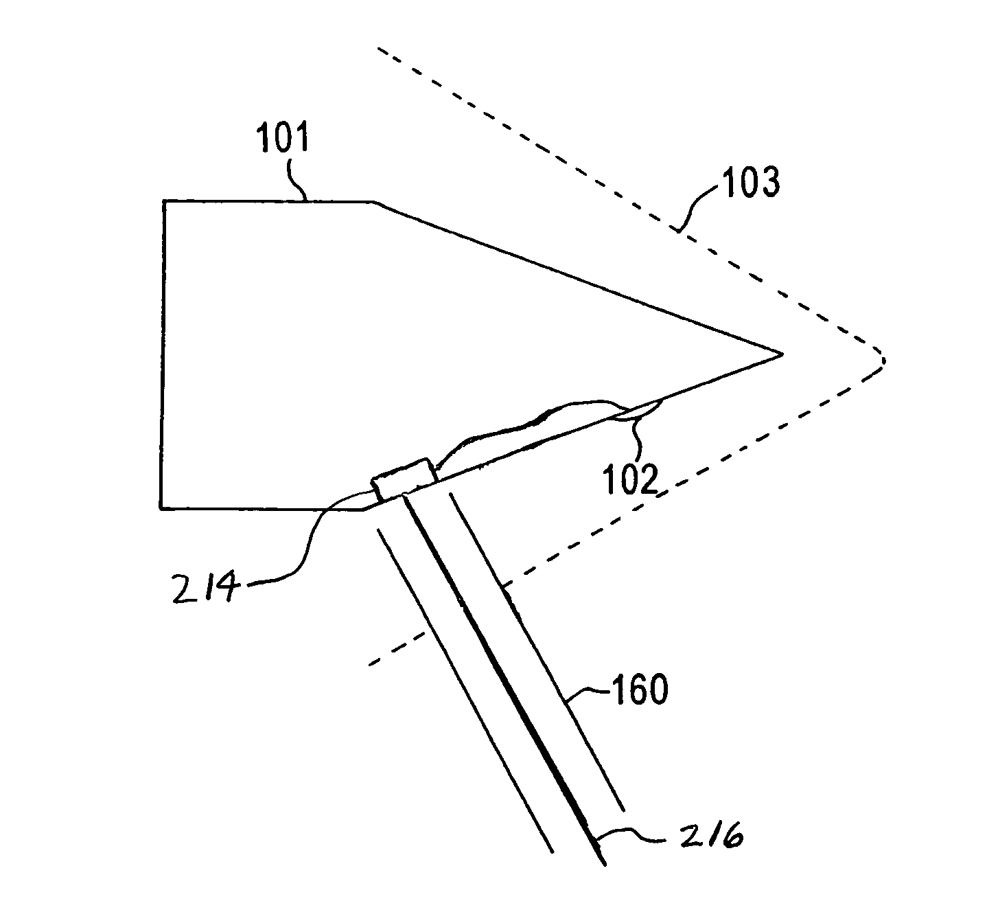
[0098]FIGS. 11A-D illustrate use of the invention with a body 101 moving to the right through a fluid 105 at supersonic speed. In FIG. 11A, the body 101 is moving to the right through the fluid 105 at supersonic speed, as indicated by a shock wave 103 ahead of the body 101. In the rest frame of the shock wave 103, or equivalently the rest frame of the body 101, the fluid 105 ahead of the shock wave is moving to the left.

[0099]The invention is not limited as to a particular body 101. For example, the body 101 could be an airplane, a missile, a launch vehicle, a projectile, a re-entry vehicle, or any subsystem or protrusion thereon, such as an engine, the body's nose, an external fuel tank, a fairing, a tail, a wing, or external instrumentation. Furthermore, the invention is not limited as to the particular fluid 105 through which the body 101 passes. Additionally, the fluid flow need only be locally supersonic to yield a shock wave 103. The body 101 also includes a port 102 through w...

example 2

[0103]FIG. 12 illustrates a use of the invention with a body 101 that is passing through a fluid 105 with a non-zero angle of attack A. The body 102 includes an energy discharge device 102 that creates a heated core along an extended path 108 through a shock wave 103 in front of the body 101. Although the extended path 108 is parallel to the motion of the body 101 through the fluid 105, the angle of the extended path 108 from energy discharge device 102 is not parallel to the body center axis (BCA) of the body 101 because of the non-zero angle of attack A of the body 101. In fact, the preferential drag reduction resulting from the off-center / asymmetric application of the heating can be used to partially or fully maintain the non-zero angle of attack A, in addition to reducing the overall drag on the body 101.

example 3

[0104]A method of increasing the energy deposition along a heated path through the use of electric discharge is illustrated in FIG. 13. A body 101 passing through a fluid 105 at supersonic speed such that a set of shock waves 103 is created adjacent to the body 101. The body includes three energy emitting mechanisms 106, 107. Two of the energy emitting mechanisms 106 are charged with a given polarity, and a third energy emitting mechanism 107 is oppositely charged. An example of an energy emitting mechanism is explained in more detail with regard to FIG. 14.

[0105]To better control the electric discharge path of the energy emitting mechanisms 106, 107, each of the energy emitting mechanisms includes an electromagnetic discharge port that is capable of ionizing a path 108 through the fluid 105. The conductive ionized paths 108 intersect at a point PI ahead of the body 101 and ahead of the shock wave 103. The ionized paths 108 provide a conductive circuit along which the oppositely cha...


PUM


Abstract

A system for modifying a shock wave formed in a fluid by a body to modify effects of the shock wave on information transferred to or from the body. The system includes an element for heating fluid along a path to form a volume of heated fluid expanding outwardly from the path, the path extending from the body and through the shock wave; mechanism for transferring the information to or from the body; and device for timing the transferring of the information relative to the heating of the fluid along the path to modify certain effects of the shock wave on the information.

Description

CROSS REFERENCE TO RELATED APPLICATIONS[0001]This application is a Continuation-In-Part of application Ser. No. 10 / 342,347, filed on Jan. 15, 2003 now U.S. Pat. No. 7,063,288, which is a Continuation-In-Part of application Ser. No. 09 / 867,752, filed on May 31, 2001 now U.S. Pat. No. 6,527,221, which claims the benefit of U.S. Provisional Application No. 60 / 208,068, filed on May 31, 2000, each of which are incorporated herein by reference.FIELD OF THE INVENTION[0002]The present invention relates to facilitating the movement of objects through a fluid and, more particularly, to modifying shock waves within the fluid.BACKGROUND OF THE INVENTION[0003]When a fluid is driven to flow at a relative speed, with respect to the fluid it encounters, that exceeds the speed of sound within the encountered fluid, one or more shock waves can develop. The driving of the fluid can occur when the fluid is pressed forward by an object or body propagating through the fluid. Alternatively, the fluid can ...

Claims


Application Information

Patent Timeline
Patent Type & Authority Patents(United States)
IPC IPC(8): H04B10/10B64C23/04B64G1/62
CPCB64C23/04B64G1/62Y10T137/0391
Inventor KREMEYER, KEVIN
Owner KREMEYER KEVIN
Learn More