Delay-line demodulator

Inactive Publication Date: 2010-01-19
FURUKAWA ELECTRIC CO LTD
View PDF4 Cites 10 Cited by
  • Summary
  • Abstract
  • Description
  • Claims
  • Application Information

AI Technical Summary

Benefits of technology

[0017]For solving the above mentioned subjects, the present inventors have found out that it is able to adjust a divergence amount of polarization by driving each of heaters on Mach-Zehnder interferometers (MZIs) facing to a wavelength plate respectively, and then invented a method for reducing the polarization.
[0023]According to the present invention as disclosed in claim 1, it becomes able to obtain a delay-line demodulator for a DQPSK signal of which the divergence amount of polarization is reduced.

Problems solved by technology

However, there is provided a problem that a quality of a communication line cannot help but become poor because of a deterioration of a signal waveform due to a decrease of a duration per one bit of a light signal affecting a characteristic of an optical fiber in a case of speeding up the line speed.
Moreover, it becomes hard to construct a network system with using a conventional fiber network because a repeater is required for such as converting a light signal into an electric signal during passing a transmission path and reconverting into a light signal therefrom, for performing a long distance transmission of the 40 Gbps level.

Method used


Image

  • Delay-line demodulator
  • Delay-line demodulator
  • Delay-line demodulator

Examples


first embodiment

The First Embodiment

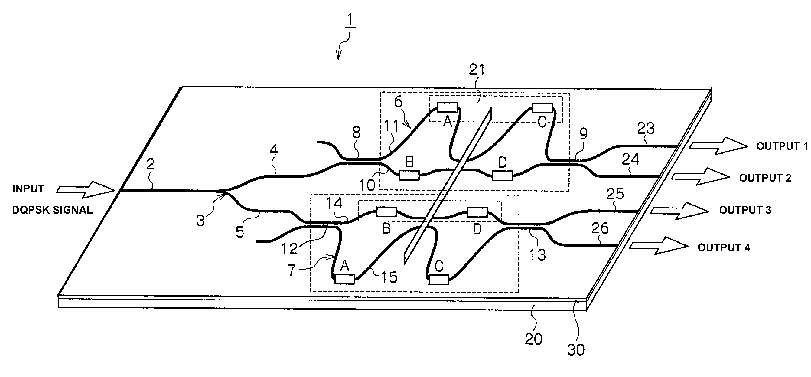
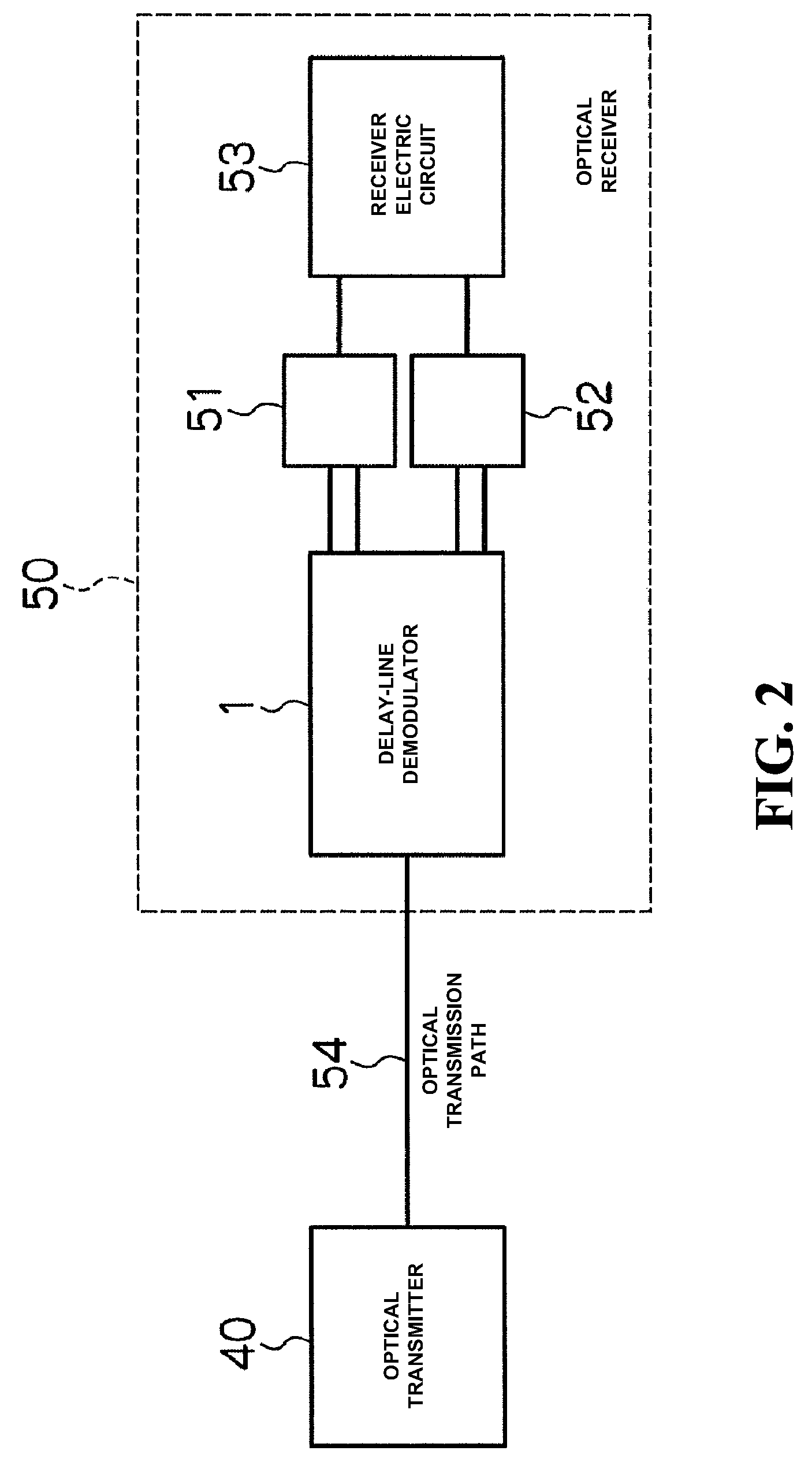
[0026]A delay-line demodulator according to the first embodiment will be described in detail below, based on FIG. 1 to FIG. 6. FIG. 1 shows a schematic configuration regarding a delay-line demodulator according to the first embodiment. FIG. 2 shows a schematic configuration of an optical transmission system (optical transmitting and receiving device) with using a DQPSK method. FIG. 3 is a graph showing a variation in a divergence amount of polarization PDλ at a time of driving a heater A and a heater D among four of heaters A, B, C and D, with changing a voltage to be applied to such the heaters. FIG. 4 is a graph showing a variation in the divergence amount of polarization PDλ at a time of driving the heater C and the heater B with changing the voltage to be applied to such the heaters. FIG. 5 is a graph showing a variation in the divergence amount of polarization PDλ at a time of driving the heater A and the heater B with changing the voltage to be applied to s...

an example

[0065]The delay-line demodulator device 1 for the DQPSK signal of 40 Gbps line speed, which comprises the one Y-branch waveguide 3, and the Mach-Zehnder interferometer circuits 6 and 7 comprised of the quartz based glass 30, is manufactured on the silicon substrate 20, by using the flame hydrolysis method (FHD method), the photolithography method, and the reactive ion etching method.

[0066]Moreover, the tantalum based heaters (thin film heaters) A to D are formed on the waveguides 10, 11, 14 and 15 in each of the Mach-Zehnder interferometer circuits 6 and 7 by using the spattering method. And then for each of such the heaters A to D, a heater length thereof is designed to be 5000 μm and a heater width thereof is designed to be 60 μm respectively. Here, it is confirmed that a value of resistances therefor are approximately the similar to therebetween. Further, the half wavelength plate 21 is inserted into each of the central parts of the two waveguides in each of the Mach-Zehnder inte...

embodiments

The Second Embodiment

[0076]FIG. 7 shows a schematic configuration regarding a delay-line demodulator 1A according to the second embodiment.

[0077]Such the delay-line demodulator 1A is a delay-line demodulator of a planar lightwave circuit (PLC) type for demodulating a DPSK signal, and is the delay-line demodulator for a DPSK signal of 40 Gbps line speed to be used for an optical transmission system with using the DPSK method.

[0078]According to such the optical transmission system, the DPSK signal is transmitted from an optical transmitter (refer to the optical transmitter 40 as shown in FIG. 2), which is modulated into phase data including a phase of a propagation wave (θ or θ+π) for two data as values (0 or 1) of individual bits comprised of data of one bit, with corresponding to a variation in values of neighboring two bits. Moreover, a DPSK signal transmitted from the optical transmitter to an optical receiver (refer to the optical receiver 50 as shown in FIG. 2) is converted into...


PUM


Abstract

A delay-line demodulator for demodulating a differential quadrature phase shift keying (DQPSK) signal is provided. The demodulator includes two Mach-Zehnder interferometers individually comprising two waveguides having different lengths therebetween and through which a light signal branched from the DQPSK signal propagates, respectively. A phase of the light signal propagating at one of the waveguides is delayed as compared to a phase of the light signal propagating at another one of the waveguides, wherein a divergence amount of polarization is adjusted by driving sets of heaters that are facing each other and sandwiching a half wavelength plate therebetween.

Description

CROSS-REFERENCE TO RELATED APPLICATIONS[0001]This application claims priority from Japanese patent application serial No. 2007-267153, filed on Oct. 12, 2007, the entire content of which is incorporated herein by reference.BACKGROUND OF THE INVENTION[0002]1. Technical Field[0003]The present invention relates to a delay-line demodulator to be used for an optical fiber communication. In particular, it relates to a delay-line demodulator comprising a Mach-Zehnder interferometer (MZI) of a planar lightwave circuit (PLC) type for demodulating a signal of such as a differential quadrature phase shift keying (DQPSK), a differential phase shift keying (DPSK), or the like, regarding the optical fiber communication using a transmission method of a dense wavelength division multiplexing (DWDM).[0004]2. Background Art[0005]In recent years, an examination for a speed up of an optical transmission system (to be a line speed of 40 Gbps) is actively performed against a backdrop of a rapid spread of...

Claims


Application Information

Patent Timeline
IPC IPC(8): G02F2/00G02B6/12H04B10/516G02F1/01H04B10/556H04B10/564H04B10/61
CPCG02F2/00H04B10/505H04B10/677
Inventor HASEGAWA, JUNICHINARA, KAZUTAKA
Owner FURUKAWA ELECTRIC CO LTD
Why Eureka
Try Eureka