Gaussian FSK modulation with more than two modulation states

a modulation state and gaussian technology, applied in the field of data transmission, can solve the problems of limited carrier frequency, limited bandwidth and power, and tight constraints on emissions outside the occupied bandwidth, so as to improve the noise performance and enhance the noise performance of the demodulator

Active Publication Date: 2010-01-26
BRITISH TELECOMM PLC
View PDF29 Cites 2 Cited by
  • Summary
  • Abstract
  • Description
  • Claims
  • Application Information

AI Technical Summary

Benefits of technology

[0017]The use of a ‘partial responsesystem, in which the next symbol starts before the channel has finished responding to the previous symbol, in combination with multiplelevel (i.e. non-binary) symbols allows particularly efficient use of bandwidth. A Gaussian filter, such as is used in the embodiment to be described, gives a well-behaved impulse response, but other filter types may also be suitable.
[0018]This modulation process will be referred to in the following as multiple-level Gaussian filtered frequency shift keying (MGFSK). In the embodiment to be described sixteen (24) levels are used, giving four user bits per symbol (uncoded) but other numbers of levels can be used. The use of a filter whose impulse response stretches over adjacent symbols enables a reduction in occupied bandwidth at the expense of some inter-symbol interference (ISI) and loss of orthogonality. The bandwidth of a modulator output Bo can be approximated to Bo=2B(1+β), where β is a dimensionless value defined as the peak frequency deviation divided by the frequency B of the baseband (modulating) signal. Consequently, the amount of deviation has to be taken into account when calculating the modulated bandwidth. This is known as Carson's rule. However, the Gaussian waveform allows the individual levels to be better discriminated than would be the case for other waveforms, allowing the occupied bandwidth to be in the narrow-band class, using a low value for the modulation index (β). If the index is β<1, the expression above approximates to Bo=2B.
[0021]The combination of multiple levels and partial response signalling results in an improved bandwidth efficiency. For example, in the embodiment to be discussed later a value of E (bit rate / occupied bandwidth) of almost 6 bits / sec / Hz is achieved which is equivalent to a 64-level QAM (Quadrature Amplitude Modulation) system Because it uses frequency modulation (as opposed to phase-shift keying), the signal is more tolerant to group delay error in the channel. Being an FM signal also means that it has a constant envelope, unlike an amplitude modulation signal, so that it is more tolerant to non-linearities including the amplitude variations caused by equalisation errors and by amplifier stages operating at or near saturation.
[0023]The noise performance of the demodulator may be enhanced by optimising the positions where samples are taken of the received waveform and also by averaging the demodulation over several symbols (typically from 3 to 8) and then performing decision feedback to determine the symbols received.
[0024]There is considerable scope to improve the noise performance through the use of digital processing and pattern recognition techniques. Whereas the QAM schemes rely on matched filtering and accurate sampling points, and demodulate symbol by symbol, the present invention works by recognising impulse responses spread over two or three symbols. Because the new scheme uses FM, it can be assumed to be linear even though the channel may be highly non-linear to amplitude and phase.

Problems solved by technology

The major limitations on capacity are available bandwidth and power, coupled with tight constraints on emissions outside the occupied bandwidth.
However, carrier frequencies are a scarce resource, and operators are not usually permitted to select a frequency of their choice.
Higher frequencies also tend to be subject to greater attenuation and require greater power to generate and amplify.
However, the greater such a difference is, the more bandwidth is required.
However, frequency shift keying has advantages in certain circumstances such as in satellite links, as the cost of setting up earth stations is affected by the required equalisation error across the signal bandwidth and this becomes more of an issue for wide-band signals and in particular for systems using phase shift keying.

Method used


Image

  • Gaussian FSK modulation with more than two modulation states
  • Gaussian FSK modulation with more than two modulation states
  • Gaussian FSK modulation with more than two modulation states

Examples


Embodiment Construction

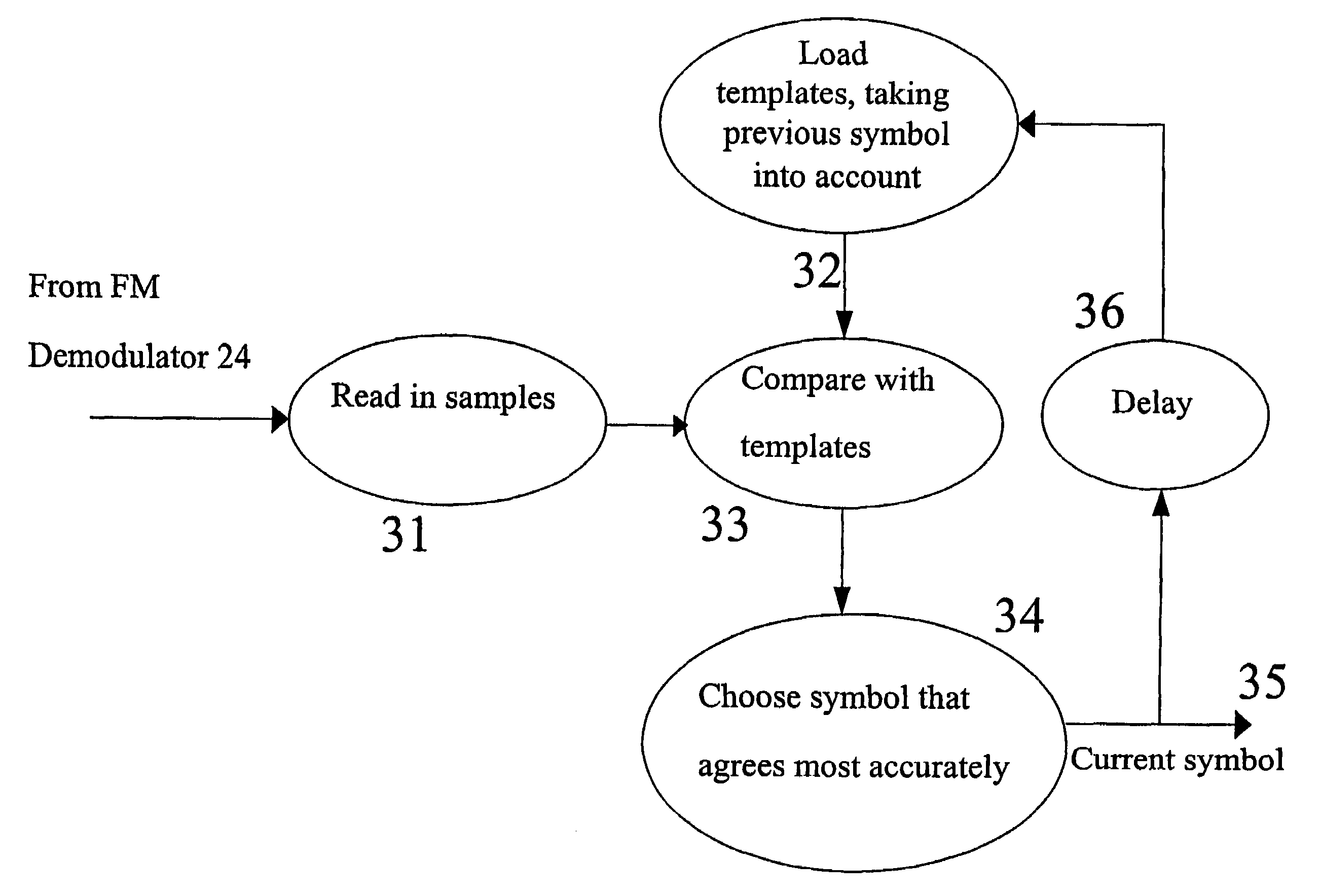
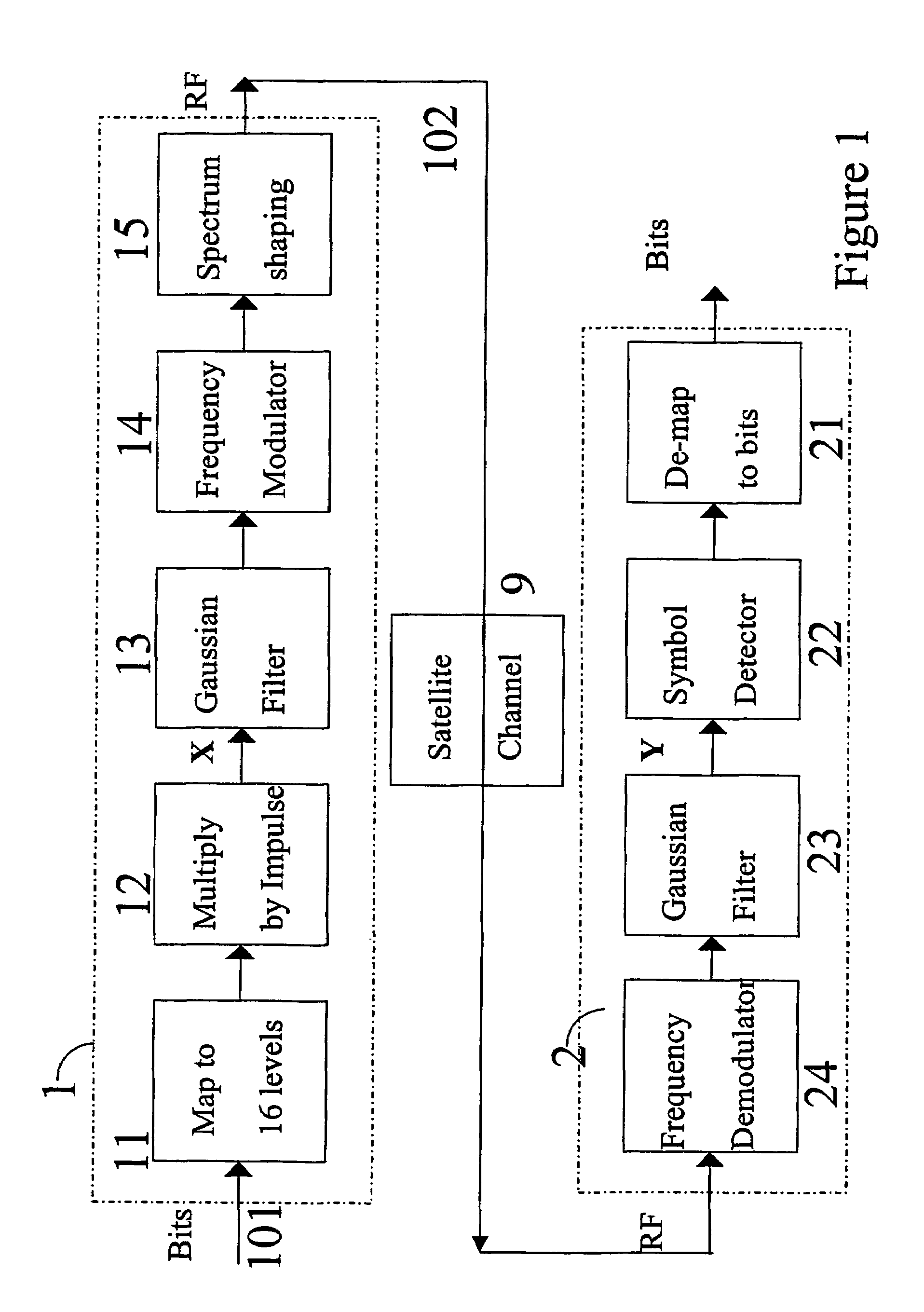
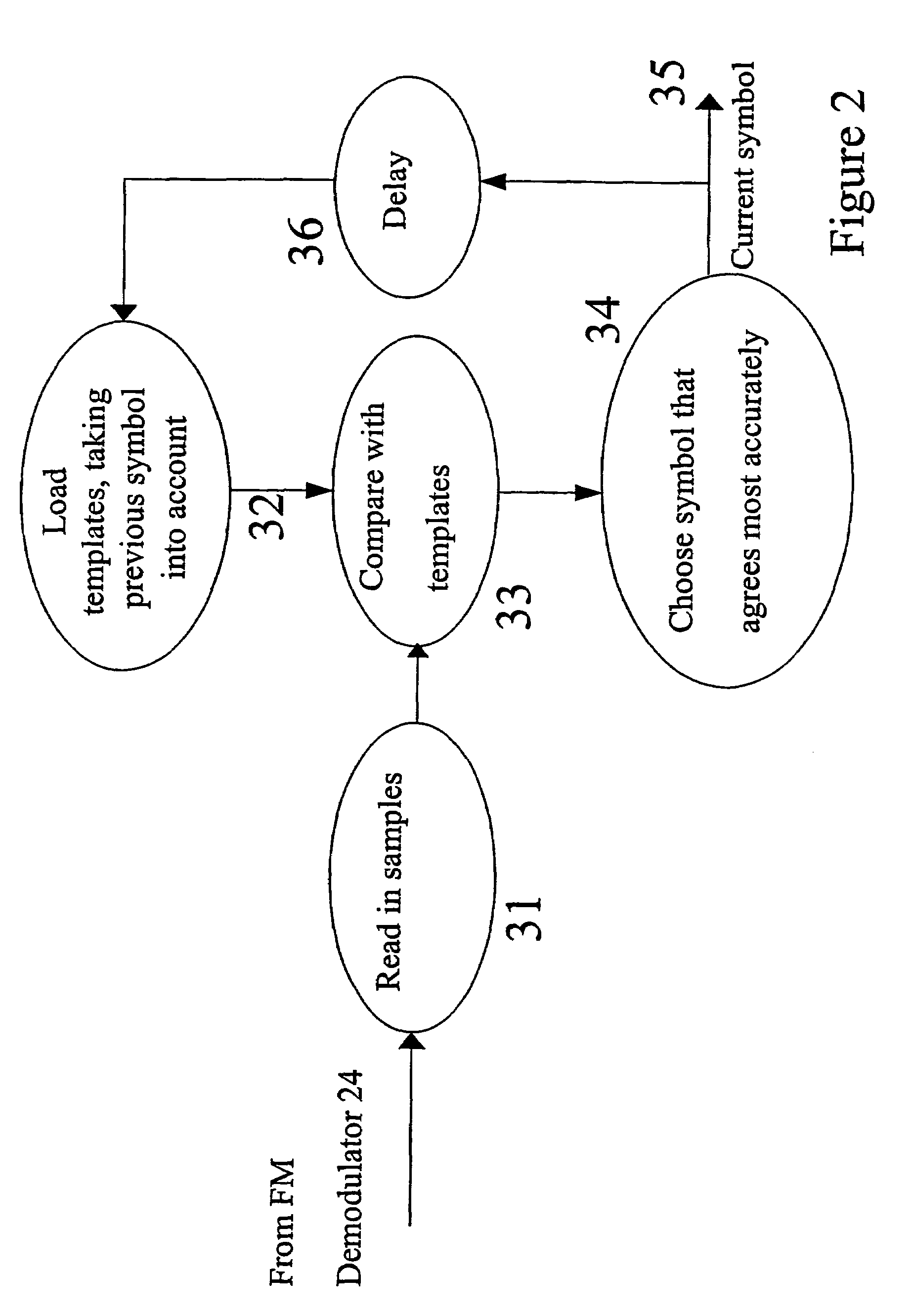
[0030]A general block diagram of the modulation and demodulation processes is shown in FIG. 1.

[0031]The modulator section 1 in the upper part of FIG. 1 begins with a mapping process 11, mapping the input bits 101 to an alphabet of sixteen symbols, which equates to four bits per symbol. The sixteen symbols are represented by different amplitudes symmetrical about zero, for example −7.5, −6.5, −5.5 . . . −0.5, +0.5 . . . +5.5, +6.5, +7.5. These are multiplied by impulses of value 1 (step 12) to produce impulses of −7.5, −6.5 . . . +6.5, +7.5 at the point labelled ‘X’ in FIG. 1, which acts as an input to the filtering process, which uses a Gaussian filter 13. The Gaussian shape of the response to the impulses generated in the previous step 12 has smooth excursions with no negative or oscillatory characteristics. This output is next applied to the frequency modulator 14. This method of modulation is very similar to the scheme used by the GSM cellular telephone system air interface, exce...


PUM


Abstract

A wireless data transmission system uses modulation onto a multi-level symbol, so that a multi-level frequency shifted signal can be generated. By using a Gaussian filter, inter-symbol interference can be introduced. The demodulation process makes use of templates corresponding to each of the possible symbol transitions, so that knowledge of previously decoded symbols can be used to decode the next one.

Description

[0001]This application is the US national phase of international application PCT / GB03 / 00186 filed 16 Jan. 2003 which designated the U.S. and claims benefit of EP 02250960.8, dated 12 Feb. 2002 and GB 0229623.4 dated 19 Dec. 2002, the entire content of each of which is hereby incorporated by reference.BACKGROUND[0002]1. Technical Field[0003]This invention relates to the transmission of data over high data-rate point-to-point and point-to-multipoint radio links. Such links are used in many different configurations, using radio transmitter and receivers which may be fixed or mobile, terrestrial or in orbit.[0004]2. Related Art[0005]The major limitations on capacity are available bandwidth and power, coupled with tight constraints on emissions outside the occupied bandwidth. These constraints require a capability to transmit data with high bandwidth efficiency while at the same time being tolerant both to equalisation error (amplitude and group delay) and to non-linearities (such as cau...

Claims


Application Information

Patent Timeline
IPC IPC(8): H04L27/10H04L7/00G06F1/14H04J3/06H04L12/24H04L27/20H04L27/233H04L29/08H04Q11/04
CPCG06F1/14H04L41/00H04L27/2334H04L27/2017
Inventor FITCH, MICHAEL RFLYNN, JASON S
Owner BRITISH TELECOMM PLC
Why Eureka
Try Eureka