Laser analytical instrument, laser analytical method, and gas leak inspection instrument

a technology of laser analysis and gas leak detection, which is applied in the direction of instruments, luminescent dosimeters, optical radiation measurement, etc., can solve the problems of reducing the generating efficiency or other troubles, increasing the cost of the device, and complicated device configuration and other problems, so as to achieve the effect of easy identification

Inactive Publication Date: 2010-02-16
HORI MASAKI +2
View PDF21 Cites 1 Cited by
  • Summary
  • Abstract
  • Description
  • Claims
  • Application Information

AI Technical Summary

Benefits of technology

[0029]According to the first and 12th inventions, the laser light is condensed in the area where the object gas of analysis exists and the laser light is imparted with the energy for causing the multiple photon ionization phenomenon or the multiple photon excitation phenomenon of the object gas of analysis at least in the condensed part. Therefore, even if the laser light has a given wavelength (fixed wavelength), it is possible to cause the multiple photon ionization phenomenon or the multiple photon excitation phenomenon in various types of gas existing in the condensed part and consequently to produce fluorescence having a wavelength corresponding to the type of the object gas of analysis in the condensed part or to the type of each constituent gas of the object gas of analysis. Therefore, it becomes possible to observe the state of the object gas of analysis (the concentration of the object gas of analysis, the concentration of each type of constituent gas of the object gas of analysis, the presence or absence of a specific type of gas, or the like) by receiving the fluorescence produced in the condensed part or analyzing the state of the fluorescence (the intensity (wavelength distribution) for each wavelength of the fluorescence, the intensity of the fluorescence having a specific wavelength, or the like)). In this instance, the laser light can be one having a given wavelength (a fixed wavelength) independently of the type of object gas of analysis or the type of each constituent gas of the object gas of analysis. Therefore, there is no need to use two lasers different in wavelength of laser light or to vary the wavelength of the laser light according to the type of the object gas of analysis. Therefore, an inexpensive and simple configuration can be achieved for the laser analytical instrument. In other words, according to the first or 12th invention, various types of gas can be analyzed with the inexpensive and simple configuration of the laser analytical instrument.
[0059]According thereto, a spatial distribution state of the gas leakage can be grasped based on the image data, and therefore it is possible to easily identify the region of the gas leakage of the inspection object.

Problems solved by technology

On the other hand, for example, regarding a fuel cell stack, it has been required to detect a gas leak before shipment or the like of the fuel cell stack since the gas leak from its body part or a pipe connected thereto leads to a reduction in generating efficiency or other troubles.
Accordingly, the conventional fluorescence analysis method has a problem that it requires a device for varying the wavelength of the laser light when analyzing various types of gas using the conventional fluorescence analysis method, which leads to a complicated device configuration and to an increase in device cost.
Furthermore, where gas is changed to plasma (dissociated electrolytically) to increase the intensity of the produced fluorescence, it is necessary to use two laser devices, which leads to a more expensive and complicated device.
Moreover, in the conventional fluorescence analysis method, some types of gas (for example, hydrogen and helium) cannot be detected as a matter of fact for the reason described below.
Under present circumstances, there is no laser device or optical component that can easily generate laser light having a wavelength in the extreme vacuum ultraviolet region.
Furthermore, the light in the extreme vacuum ultraviolet region is immediately absorbed and attenuated in the air and therefore it is very difficult to irradiate a desired position with that kind of light.
Accordingly, monoatomic gas (rare gas) such as helium or argon and a hydrogen atom cannot be detected by the Raman scattering method, by which the object gas of analysis is limited disadvantageously.
Furthermore, in the spontaneous Raman scattering of the Raman scattering method, it is difficult to detect a very small amount of gas in the air.
Still further, in the stimulated Raman scattering of the Raman scattering method, two different kinds of laser light are needed, which leads to a large-sized or complicated device configuration and to an expensive device disadvantageously.
Regarding the method using the hydrogen visualization agent as described in the Patent Document 3, it is difficult to supply the hydrogen visualization agent, which is liquid, only to a region within a specific small area of a fuel cell stack, for example, when it is attempted to detect a leakage of the hydrogen while supplying the hydrogen to the fuel cell stack.
Therefore, it is difficult to identify the region of occurrence of a gas leak accurately using the method.
Moreover, it has a problem of requiring a work for removing hydrogen visualization agent adhered to the surface of the fuel cell stack after the inspection.
This method, however, requires a work for drying the fuel cell stack after the inspection.

Method used


Image

  • Laser analytical instrument, laser analytical method, and gas leak inspection instrument
  • Laser analytical instrument, laser analytical method, and gas leak inspection instrument
  • Laser analytical instrument, laser analytical method, and gas leak inspection instrument

Examples


example 1

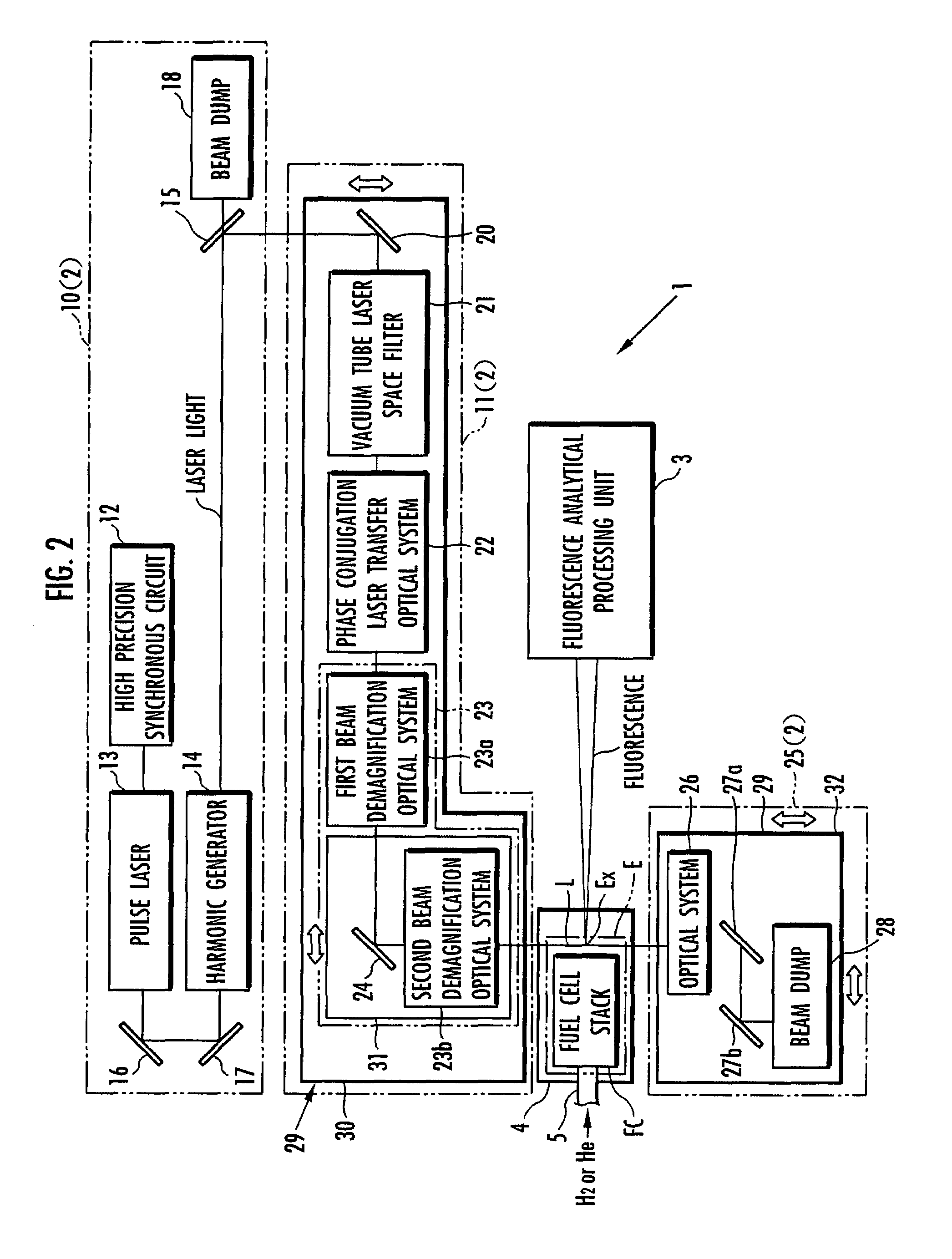
[0117]A sealed glass tube containing a given type of gas was placed within the target inspection region E of the instrument 1 according to the first embodiment. In this condition, the laser light generating / transfer unit 2 was operated to irradiate the glass tube with the laser light L so that the condensed part Ex is located in the glass tube. During this time, the fluorescence analytical processing unit 3 received fluorescence produced in the glass tube and measured a wavelength distribution of the fluorescence on the basis of the view data obtained from the analyzer 48. The gas sealed in the glass tube includes four types: air, nitrogen, helium, and hydrogen.

[0118]The measurement result is shown in FIG. 5(a) to FIG. 5(d). FIG. 5(a) to FIG. 5(d) each show the wavelength distribution of the fluorescence when the gas sealed in the glass tube is air, nitrogen, helium, or hydrogen (more specifically, the intensity of the fluorescence for each wavelength within the range of 400 to 800 ...

example 2

[0123]Preparing a sealed glass tube containing nitrogen gas that includes hydrogen (hereinafter, referred to as glass tube 1) and a sealed glass tube containing air gas that includes hydrogen (hereinafter, referred to as glass tube 2), the glass tubes 1 and 2 were placed within the target inspection region E of the instrument 1 according to the first embodiment. In this condition, the laser light generating / transfer unit 2 was operated to irradiate the glass tubes 1 and 2 with the laser light L with the condensed part Ex being located in the glass tubes 1 and 2. During this time, the fluorescence analytical processing unit 3 received fluorescence produced in the glass tubes 1 and 2 and measured a wavelength distribution of the fluorescence in the wavelength range of 653 nm to 663 nm on the basis of the view data obtained from the analyzer 48. In this instance, for the glass tube 1, the concentrations of the hydrogen were set to four types: 50 ppm, 100 ppm, 500 ppm, and 1000 ppm. For...


PUM


Abstract

Laser light generated from laser light generating means (10) is fed through laser light transfer means (11) including a demagnification optical system (23) so as to be condensed in a part Ex where an object gas of analysis exists. The laser light is imparted with energy for causing a multiple photon excitation phenomenon or a multiple photon ionization phenomenon of gas in the condensed part Ex. The energy of the laser light is large enough for 17 eV or higher energy to be injected into a hydrogen molecule when the object gas of analysis is hydrogen and for 23 eV or higher energy to be injected into a helium atom when the object gas of analysis is helium. For example, the intensity of the laser light in the condensed part Ex is 1014 W / cm2 or higher. This provides a laser analytical instrument capable of observing various types of gas through an inexpensive and simple arrangement.

Description

RELATED APPLICATIONS[0001]This application is a 35 U.S.C. 371 national stage filing of International Application No. PCT / JP2005 / 012942, filed 13 Jul. 2005, which claims priority to Japanese Patent Application No. 2004-207794 filed on 14 Jul. 2004 in Japan. The contents of the aforementioned applications are hereby incorporated by reference.TECHNICAL FIELD[0002]The present invention relates to an instrument and method for analyzing gas using laser light and to an instrument for inspecting a fuel cell stack or a hydrogen supply / discharge system for supplying or discharging hydrogen to or from the fuel cell stack for a gas leak by using laser light.BACKGROUND ART[0003]There is already known a method of analyzing whether there is a specific type of object gas of analysis, gas concentration or the like by exciting the gas using laser light to produce fluorescence and analyzing the state (the wavelength, the intensity of the wavelength, and so forth) of the fluorescence (for example, refe...

Claims


Application Information

Patent Timeline
Patent Type & Authority Patents(United States)
IPC IPC(8): G01J1/58
CPCG01M3/226G01M3/38G01N21/6402H01M8/04089Y02E60/50
Inventor HAYANO, RYUGOHORI, MASAKI
Owner HORI MASAKI
Why Eureka
Try Eureka