Motor module

a technology of motor modules and motor windings, which is applied in the direction of rotating magnets, mechanical energy handling, and synchronous machines with stationary armatures, etc., can solve the problems of poor rotation efficiency of the motor system pb>10/b>, the volume of the above-mentioned miniature motor modules may not be miniaturized, and the use of a lot of conductive magnet plates, etc., to achieve the effect of minimizing the structure of the motor module, and effective reduction of the yield rate of the motor

Active Publication Date: 2010-02-16
METAL INDS RES & DEV CENT
View PDF13 Cites 24 Cited by
  • Summary
  • Abstract
  • Description
  • Claims
  • Application Information

AI Technical Summary

Benefits of technology

[0013]By implementation of the present invention, because a semiconductor wiring process is adopted for the wirings of the electric unit, the signal circuits and the motor windings are formed at the same time, so that the volume and the thickness in the axis direction of the wires of the whole motor windings wouldn't be increased, that is suitable for simplifying and minimizing structure of motor modules. Besides, because the signal circuits and the motor windings are integrately designed, they can be formed on the PCB at the same time; therefore, the yield rate of the wires of the motor winding can be effectively improved. Also, because it adopts a semiconductor process, it can be combined to the current circuit board manufacturing processes. Moreover, because the electric unit and the magnetic rotor unit are designed as individual modules, the components of motor can be effectively reduced, so as to improve the assembly rate of motor and achieve the purpose of reducing motor volume.

Problems solved by technology

However, volumes of the above-mentioned miniature motor modules may not be miniaturized because their motor system is too complex.
In addition, a lot of conductive magnet plates have to be used; however, poor rotation efficiency of the motor system P10 may still occur because of effects of unsmooth operation or large cogging torque.
Besides, if the rate of slots to be occupied by coils of the motor windings is too high, the thickness of the whole motor system P10 will be increased, so that the purpose of the miniaturization may not be achieved.
Therefore, the components of the above-mentioned motor system P10 would not be easily reduced, so that the difficulty for assembly is increased and the mechanical automation for assembling is also hard to be applied.
Besides, there is also a problem when the motor system P10 is connected to the driving circuits of the circuit board for driving in final assembly stage; therefore, the space size of the motor becomes harder to be reduced.
From above facts, currently there exist problems that the motor system P10 of the miniature motor module and the circuit board for driving are unable to be implemented as a modular design.
Therefore, it can be seen that the miniature motor modules is still unable to achieve simplification and compactness, and the problems are needed to be overcome.

Method used


Image

  • Motor module
  • Motor module
  • Motor module

Examples


first embodiment

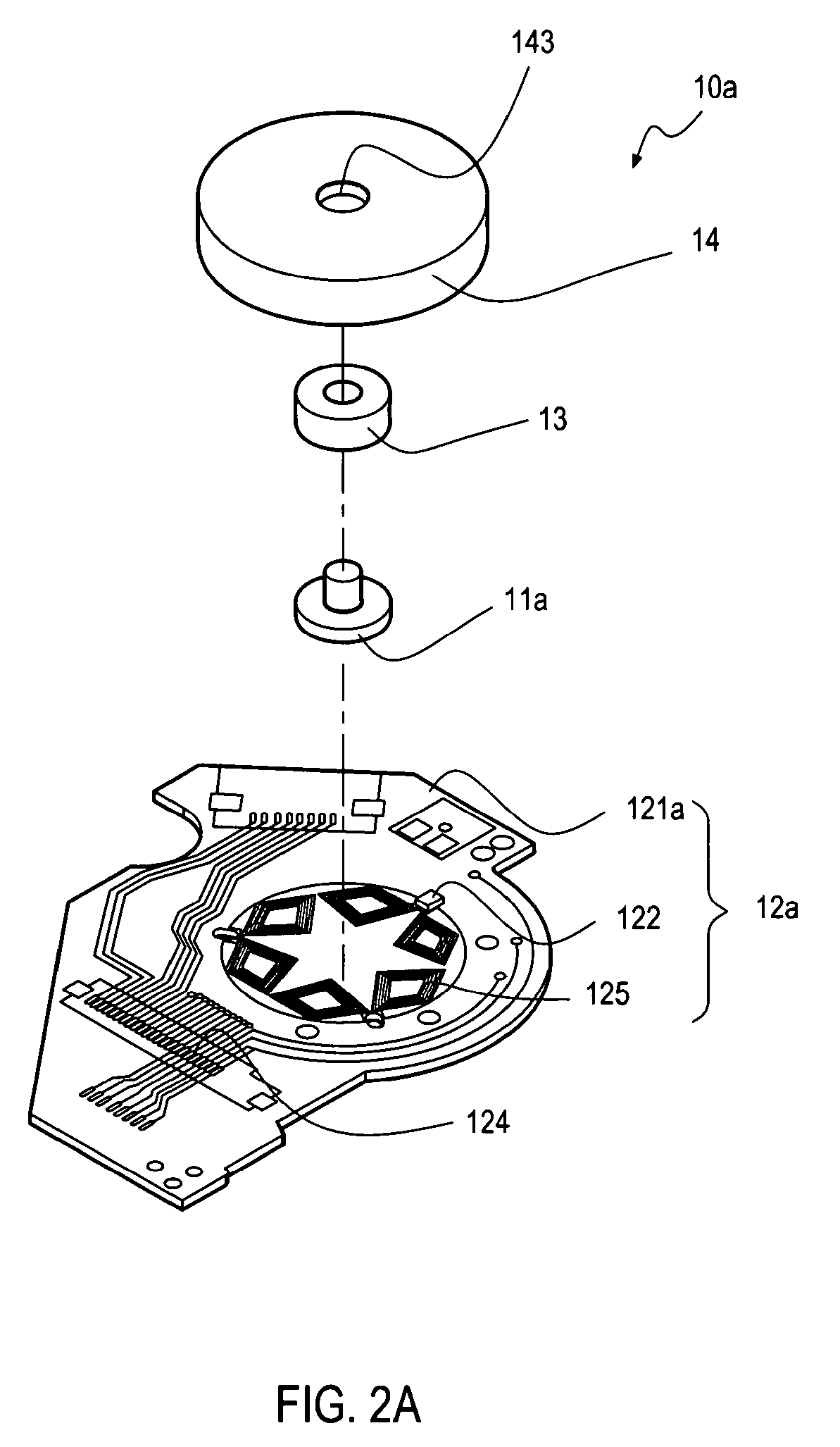
[0050]As shown in FIGS. 2A and 2B, a motor module 10a of a first embodiment in the present invention comprises a bearing housing 11a, an electric unit 12a, a bearing 13, and a magnetic rotor unit 14. The bearing housing 11a has a loading base 111, and a protruding portion 112 is extending from one end of the loading base 111. In the FIGS of the embodiment, the diameter of the loading base 111 is larger than that of the protruding portion 112. However, in other practices, the diameter of the loading base 111 may equal to or smaller than that of the protruding portion 112. Also, the electric unit 12a includes a PCB 121a and a plurality of sensing elements 122. The aforesaid loading base 111 is disposed on the PCB 121a. In addition, by means of wirings, signal circuits 124 and motor windings 125 are formed on the PCB 121a, where is around the disposed loading base 111. And the aforesaid plurality of sensing elements 122 is disposed around the motor windings 125.

[0051]Referring to FIGS....

fourth embodiment

[0058]Referring to FIG. 5, it is a motor module 10e of the present invention, wherein the bottom plate 20 has a punch hole 21, where is corresponding to the through hole 1211 of the PCB 121b. One end of the loading base 111 has a mounting portion 114 extended therefrom. That is, the bearing housing 11e further includes a mounting portion 114. Therefore, by inserting the mounting portion 114 into the punch hole 21 of the bottom plate 20, the bearing housing 11e can be inserted into the through hole 1211 of the PCB 121b and stackedly disposed on the bottom plate 20. Besides, because the loading base 111 is disposed on the through hole 1211, it can be combined to the PCB 121b.

[0059]Referring to FIG. 6, the magnetic rotor unit 14 of the motor module 10a of the first embodiment can be disposed with a carrier 15. In the embodiment, the carrier 15 is disposed on the upper lid 141, and the carrier 15 can be used to carry an optical disk, which is the motor module 10f a fifth embodiment of ...

eleventh embodiment

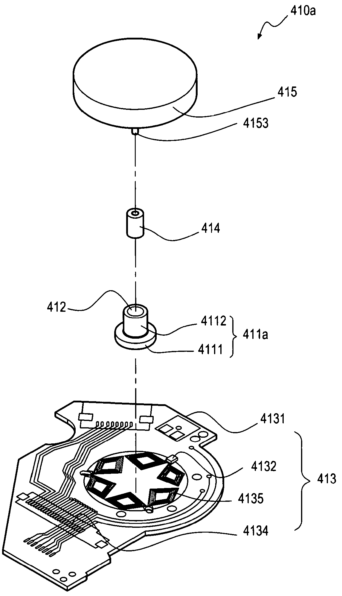
[0066]Referring to FIGS. 12A and 12B, in the motor module of the present invention, the motor module 410a in an eleventh embodiment comprises a bearing housing 411a, a hole 412, an electric unit 413, a bearing 414, and a magnetic rotor unit 415. The bearing housing 411a has a loading base 4111, and one end of the loading base 4111 has a protruding portion 4112. In the FIGS of the embodiment, the diameter of the loading base 4111 is larger than that of the protruding portion 4112. However, in other practices, the diameter of the loading base 4111 may equal to or smaller than that of the protruding portion 4112. Besides, the hole 412 penetrates the entire protruding portion 4112, and extends and passes through the loading base 4111 for disposing the bearing 414 therein. In other applications, the hole 412 may be a step-shaped hole, and penetrates the entire protruding portion 4112 and the loading base 4111 for disposing the bearing 414 therein. Moreover, the electric unit 413 comprise...


PUM

PropertyMeasurementUnit
electric angleaaaaaaaaaa
areaaaaaaaaaaa
volumesaaaaaaaaaa

Abstract

A motor module includes a bearing housing having a loading base, an electric unit, a bearing, and a magnetic rotor unit disposed on the bearing. In addition, a protruding portion is extending from the loading base, and the electric unit includes a printed circuit board (PCB) and sensing elements, wherein the PCB is utilized for disposing the loading base thereon. Moreover, signal circuits and motor windings are formed on the PCB around the loading base, the sensing elements are disposed around the motor windings, and the bearing is disposed at the protruding portion. Besides, the magnetic rotor unit is disposed on the motor windings, keeping a gap with the PCB; therefore, when electric current passes the motor windings, the magnetic rotor unit and the motor windings generate a flux linkage induction, so as to drive the magnetic rotor unit to rotate relative to the PCB.

Description

[0001]This application claims the benefit of Taiwan Patent Application No. 095148056, filed on Dec. 20, 2006, Taiwan Patent Application No. 095148054, filed on Dec. 20, 2006, Taiwan Patent Application No. 096101001, filed on Jan. 10, 2007, and Taiwan Patent Application No. 096101000, filed on Jan. 10, 2007, which are hereby incorporated by reference for all purposes as if fully set forth herein.BACKGROUND OF THE INVENTION[0002]1. Field of Invention[0003]The present invention relates to a motor module, and more particularly, to a modular and miniature assembly motor.[0004]2. Related Art[0005]Miniature motor modules in current practice include a motor system and a circuit board for driving. In most of the miniature motor modules, the motor system is firstly assembled; then, signal lines and power lines pre-installed inside the motor system are pulled out to connect with the circuit board, so as to drive the motor system of the miniature motor module to operate; therefore, parts to be ...

Claims


Application Information

Patent Timeline
Patent Type & Authority Patents(United States)
IPC IPC(8): H02K5/16
CPCH02K5/1737H02K7/06H02K7/061H02K7/14H02K21/24H02K29/08H02K5/1677H02K11/0073H02K3/26Y10T29/49009H02K2211/03H02K11/33
Inventor TSAI, MING-CHINHUANG, GUANG-MIAOHUANG, CHIEN-CHINHSU, LIANG-YITSAI, MI-CHING
Owner METAL INDS RES & DEV CENT
Why Eureka
Try Eureka