Blade clearance system for a turbine engine

a turbine engine and blade clearance technology, which is applied in the direction of machines/engines, liquid fuel engines, lighting and heating apparatus, etc., can solve the problems of blade damage, affecting performance and efficiency, and the operational efficiency of the turbine engine is less than the theoretical maximum, so as to reduce the gap, increase the efficiency of the turbine engine, and reduce the amount of combustion gas

Inactive Publication Date: 2010-03-30
SIEMENS ENERGY INC
View PDF22 Cites 46 Cited by
  • Summary
  • Abstract
  • Description
  • Claims
  • Application Information

AI Technical Summary

Benefits of technology

[0008]The present disclosure is directed to a blade gap control system for reducing a gap formed between blades and blade rings or ring segments in turbine engines. Reducing the gap increases the efficiency of the turbine engine by reducing the amount of combustion gases flowing around the blades rather than being compressed by or otherwise flowing through the blades. The blade gap control system may be configured to enable the turbine engine to go through start up conditions, through a pinch point where the tips of the blades are closest to the blade rings and into a steady state condition. The blade gap control system may be configured to reduce the size of the gap at various operating conditions by moving the blade rings relative to the blade tips. Axial movement of the blade rings relative to the blade tips reduce the gap between the tips of blades and blade rings in turbine engines in which the tips of the blades are positioned at an acute angle relative to a rotational axis and the blade rings are positioned in a similar manner.
[0013]The one or more upstream and downstream plenums can be first and second plenums, with the first and second plenums being selectively pressurized to move the blade ring axially relative to the blade tips to adjust the gap. The radially inner wall of the blade ring can be at an acute angle with respect to the rotational axis and can be substantially equal to a tip angle defined by the blade tips and the rotational axis. The blade clearance control system can be in the compressor section of the turbine engine and can also be in the turbine section. The gap control system may have a second linkage, with the first linkage being pivotally connected at one end to the outer casing and at the other end to the second linkage. The second linkage can amplify the thermal expansion or contraction of the first linkage.
[0015]An advantage of this invention is that the blade gap control system enables blades to be brought through a pinch point without the blade tips contacting the blade rings and enables the gaps between the blades tips and the blade rings to be reduced at steady state operating conditions to increase the efficiency of the engine.

Problems solved by technology

Contact of the blade tips may cause damage to the blades.
Furthermore, designing the gap between the blade tips and the blade rings for the pinch point often results in a gap at steady state conditions that is larger than desired because the gap and combustion gases flowing therethrough adversely affect performance and efficiency.
During engine operation, fluid leakage through clearances 22 in the compressor section 10 contributes to system losses, making the operational efficiency of a turbine engine less than the theoretical maximum.
Small clearances are desired to keep air leakage to a minimum; however, it is critical to maintain a clearance between the rotating and stationary components at all times. Rubbing of any of the rotating and stationary components can lead to substantial component damage, performance degradation, and extended outages.

Method used


Image

  • Blade clearance system for a turbine engine
  • Blade clearance system for a turbine engine
  • Blade clearance system for a turbine engine

Examples


Embodiment Construction

[0026]Embodiments of the present invention address the shortcomings of prior blade tip clearance or gap control systems by providing a blade ring adapted for movement relative to the blade tips. Exemplary embodiments will be explained in connection with various possible clearance control systems and methods, but the detailed description is intended only as exemplary. Exemplary embodiments will be shown in FIGS. 3-8, but the present disclosure is not limited to the illustrated structure or application.

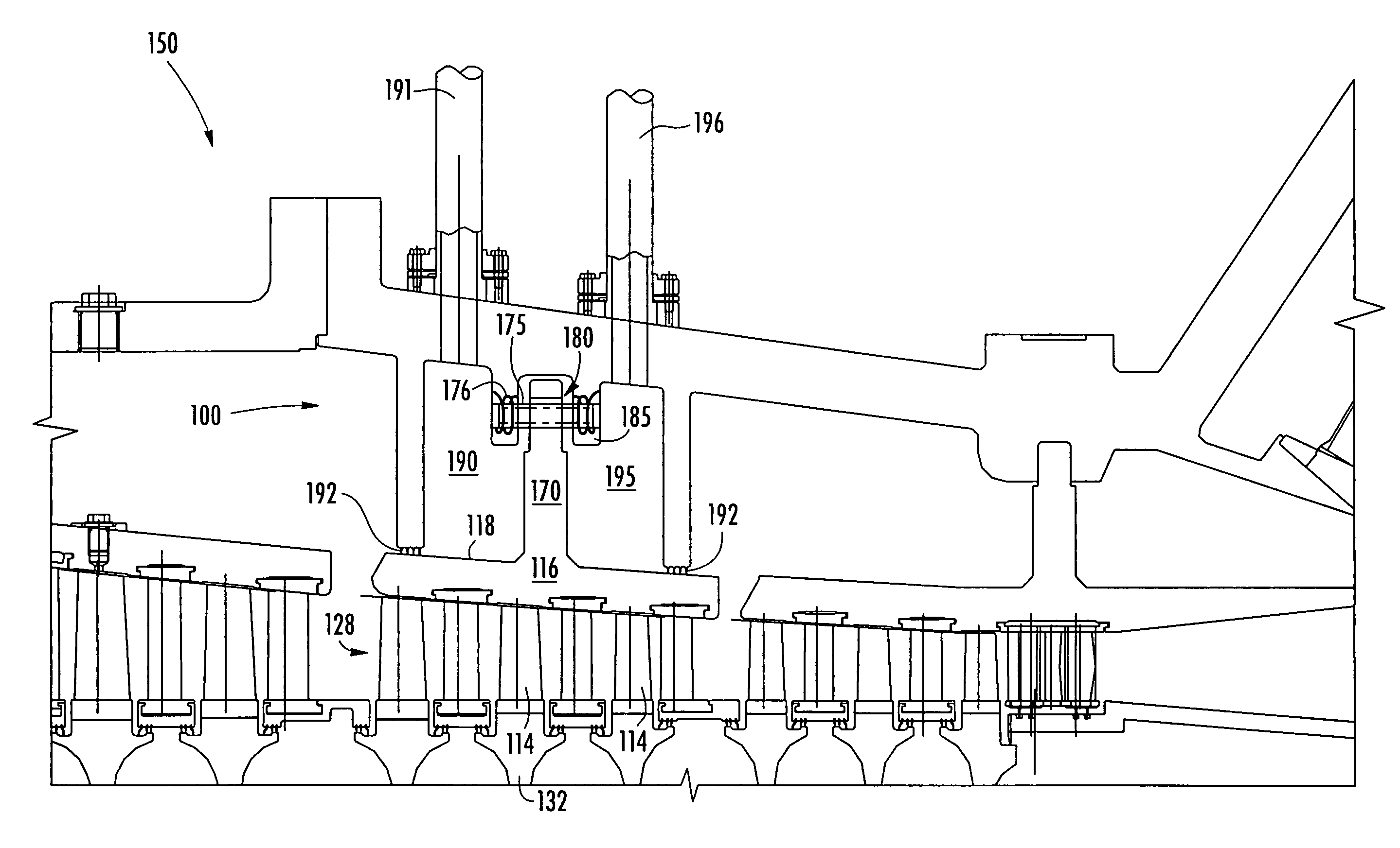
[0027]Referring to FIGS. 3-6, a first exemplary embodiment of a blade gap control system 100 may reduce a gap 112 formed between blades 114 and blade ring 116 in the turbine engine. Reducing the gap 112 increases the efficiency of the turbine engine by reducing the amount of air flowing around the blades 114 rather than being compressed by the blades 114. The blade gap control system 100 may be configured to enable the turbine engine 150 to go through start up conditions, through a pinc...


PUM


Abstract

A blade gap control system configured to move a blade ring of a turbine engine relative to a blade assembly to reduce the gaps between the tips of the blades and the blade rings to increase the efficiency of the turbine engine is provided. The blade rings can be at an acute angle with respect to the rotational axis of the blade assembly. The axial movement of the blade ring can be done by a pressure differential supplied across the blade ring, the thermal expansion and / or contraction of a linkage or by a piston.

Description

FIELD OF THE INVENTION[0001]This invention is directed generally to turbine engines, and more particularly to systems for reducing the gap between the tips of rotatable blades and blade rings.BACKGROUND[0002]Typically, gas turbine engines include a compressor for compressing air, a combustor for mixing the compressed air with fuel and igniting the mixture, and a blade assembly for producing power. Combustors often operate at high temperatures that may exceed 2,500 degrees Fahrenheit. Typical turbine combustor configurations expose blade assemblies to these high temperatures. As a result, blades must be made of materials capable of withstanding such high temperatures. Blades and other components often contain cooling systems for prolonging the life of the blades and reducing the likelihood of failure as a result of excessive temperatures.[0003]Blades typically extend radially from a rotor assembly and terminate at a tip within close proximity of the blade rings (in the compressor sec...

Claims


Application Information

Patent Timeline
Patent Type & Authority Patents(United States)
IPC IPC(8): F01D11/20
CPCF01D11/20F01D11/22F01D11/24F05D2300/505
Inventor PAPROTNA, HUBERTUS EDWARDBERTSCH, ORAN
Owner SIEMENS ENERGY INC
Why Eureka
Try Eureka