
Elevated endring birdcage antenna for MRI applications

a bird cage antenna and antenna technology, applied in applications, instruments, using reradiation, etc., can solve the problems of affecting the image quality of the system, increasing image shading, abrasion or burn to patient tissue, etc., to reduce phase delays, reduce inductance and enable capacitance to increase, the effect of increasing the impedan

Active Publication Date: 2010-03-30
GE MEDICAL SYST GLOBAL TECH CO LLC
View PDF5 Cites 21 Cited by
  • Summary
  • Abstract
  • Description
  • Claims
  • Application Information

AI Technical Summary

Benefits of technology

This configuration improves image quality, reduces power consumption, and minimizes patient heating by effectively shortening the center ring to ground, ensuring symmetry and reducing electromagnetic field interactions, thus enhancing the overall performance of high-field MR scanning.

Problems solved by technology

Such a strong interaction substantially degrades the homogeneity of the B1 field and thus negatively affects the image quality of the system and can cause an increase in image shading.
Increased patient heating can result in abrasions or burns to patient tissue.
In addition, the high static fields reduce coil efficiency and increase power requirements.

Method used


Image

  • Elevated endring birdcage antenna for MRI applications
  • Elevated endring birdcage antenna for MRI applications
  • Elevated endring birdcage antenna for MRI applications

Examples


Embodiment Construction

[0017]In the following figures the same reference numerals will be used to refer to the same components. While the present invention is described with respect to an apparatus and system for performing high field magnetic resonance (MR) scanning and imaging of a body, the following apparatus and system is capable of being adapted for various purposes including: MR imaging systems, MR spectroscopy systems, and other similar applications known in the art.

[0018]In the following description, various operating parameters and components are described for one constructed embodiment. These specific parameters and components are included as examples and are not meant to be limiting.

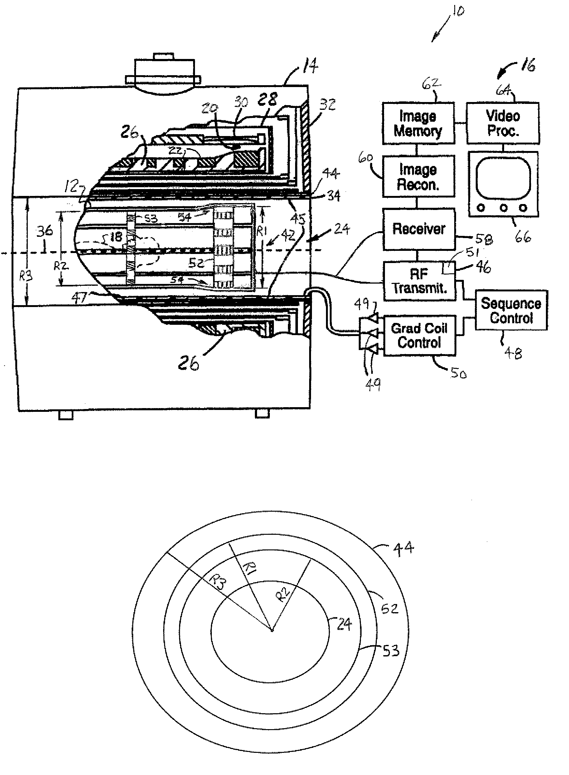
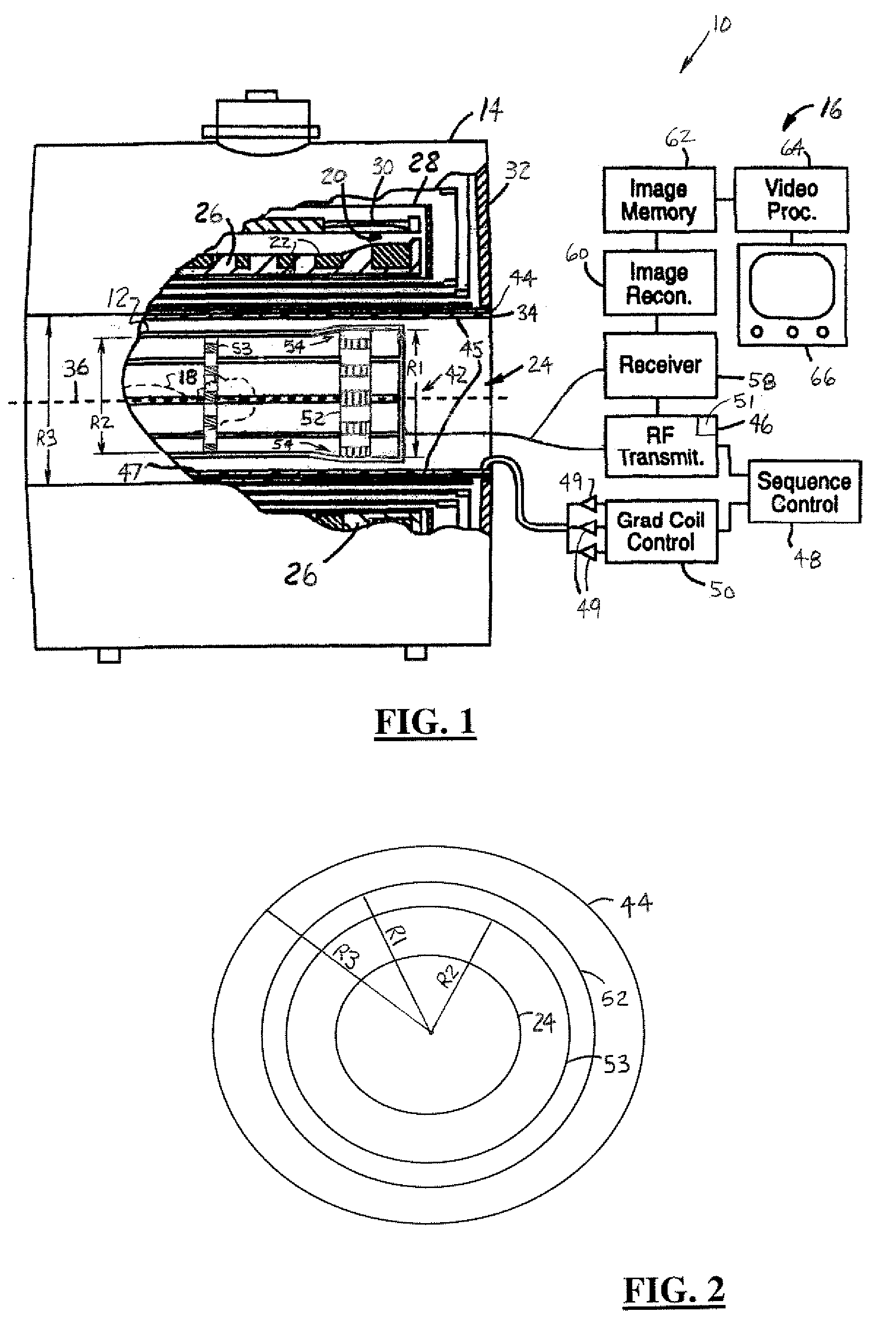
[0019]Referring now to FIG. 1, a cross-sectional side and block diagrammatic view of a MR imaging system 10 utilizing an imaging system body coil 12 in accordance with an embodiment of the present invention is shown. The imaging system 10 includes a static magnet structure 14 (a cylindrical structure) and a signal ...


PUM


Abstract

An imaging coil (12) includes multiple end rings (52). A center ring (53) extends parallel to and is coupled between the end rings (52). Multiple legs (86) are coupled between the end rings (52) and the center ring (53). The end rings (52) may have a first radius (R1) that is greater than a second radius (R2) of the center ring (53). The imaging coil (12) may include more than 16 legs. The imaging coil (12) may include multiple capacitor groupings (98) coupled along the end rings (52), each capacitor grouping (98) has multiple capacitors (102) with a coverage area width (W) greater than 5.0 cm. The center ring (53) may be coupled to a ground reference (110) and has low impedance such that the center ring (53) is effectively shorted to the ground reference (110).

Description

BACKGROUND OF INVENTION[0001]The present invention relates generally to magnetic resonance (MR) imaging systems, and more particularly, to an apparatus and system for performing high field MR scanning and imaging of a body. In magnetic resonance imaging, a patient is typically positioned within a strong, temporally constant or static magnetic field, referred to as the B0 field. A time series of magnetic field gradient pulses, for encoding spatial location, are applied across a region of interest within the magnetic field. Concurrently, radio frequency (RF) pulses are applied to induce and manipulate the magnetic resonance of magnetic dipoles in the region of interest. An assembly of RF transmitting and receiving coils is positioned over portions of the patient to excite and receive the radio frequency magnetic resonance signals within the region of interest. The RF magnetic field, generated by the RF pulses, is referred to as the B1 field.[0002]The MR imaging systems that use a low ...

Claims


Application Information

Patent Timeline
Patent Type & Authority Patents(United States)
IPC IPC(8): G01V3/00G01R33/34
CPCG01R33/34046
Inventor WEYERS, DANIEL J.KEREN, DAVIDKINSEY, KEVINBOSKAMP, ED B.
Owner GE MEDICAL SYST GLOBAL TECH CO LLC
Learn More