Method and apparatus for venous drainage and retrograde coronary perfusion

a technology of retrograde coronary perfusion and venous drainage, which is applied in the direction of balloon catheters, surgery, other medical devices, etc., can solve the problems of multiple cannulae, ineffective and incomplete, and difficulty in antegrade perfusion

Inactive Publication Date: 2010-04-13
INDIAN WELLS MEDICAL
View PDF5 Cites 7 Cited by
  • Summary
  • Abstract
  • Description
  • Claims
  • Application Information

AI Technical Summary

Benefits of technology

[0008]The invention is a cannula for performing venous drainage and retrograde perfusion of the heart during cardiac bypass surgery. A single multi-lumen cannula of the present invention can perform the same function as multiple cannulae currently used. The cannula of the invention for cardioplegic administration can improve the protection of a heart during periods of ischemia such as occurs during open-heart surgery. The cannula is preferably fabricated from materials, which are biocompatible for the intended use.
[0011]The cannula may be placed into the vena cava, for example, via a route through the internal jugular vein, cranial vena cava, femoral vein, or brachial vein. A smaller diameter cannula may be placed through any of the smaller venous access ports. The use of smaller venous access ports may be enabled by use of a pump or vacuum powered venous drainage system, typically external to the cannula. In one embodiment, the catheter or cannula combines the functions of several catheters currently used in cardiac surgery. A single catheter, rather than multiple catheters, facilitates the surgery and improves the surgical field because extra cannulae do not obstruct the operative field. In addition, the number of individual catheters is reduced, providing a more cost effective method for cardiac surgery. Most importantly, improved cardiac protection is achieved compared to that of standard retrograde perfusion cannulae.
[0013]The cannula of the present invention provides for venous drainage and simultaneous retrograde cardioplegia delivery into the coronary sinus of the heart so that the myocardium of both the right and left heart is perfused. In doing so, the coronary sinus is pressurized. Optionally, some or all of the right atrium is pressurized. Since such pressurization is unnatural for the thin walls of the right atrium, the catheter or cannula, in one embodiment, provides structures that protect the walls of the right atrium from the high perfusion pressures and minimize the risk of wall rupture. These protective structures include double wall balloons that inflate to approximate the interior of the right atrium. The space between the inner wall and the outer wall is ribbed or channeled so that gaps are maintained when a vacuum is drawn in the space between the outer wall and the inner wall of the balloon. The vacuum is drawn through the cannula by a vacuum applied at the proximal end of the cannula by way of a connector. The venous drainage cannula runs through the center of the balloon and allows for venous blood drainage from both the superior and inferior vena cava. The balloon further comprises a walled off region that is disposed laterally relative to the venous drainage cannula and permits pressurization of the coronary sinus with cardioplegia solution which is introduced at the proximal end of the cannula and which flows through a lumen in the cannula to reach the walled-off region. In one embodiment, the protection structure eliminates the need for the occlusive balloons in the vena cava.
[0015]Since the cardioplegia cannula does not cannulate the coronary sinus, it will perfuse both the left and right side of the heart. Perfusion of the right heart may be very important in obtaining optimal patient outcomes following cardiopulmonary bypass. In addition, cold cardioplegic solution will bathe the endomyocardium of the right ventricle aiding in myocardial protection of the right heart.

Problems solved by technology

For some patients, such as those suffering from critical coronary artery stenosis and aortic valve disease, antegrade perfusion may be difficult, inefficient and incomplete.
The problem with prior art methods is that either the right or left heart will be perfused, but not both, since the right coronary veins come off the coronary sinus at an angle and are not cannulated by current catheters that cannulate the left coronary veins.
The multiple cannulae are obstacles and restrict visibility in the surgical arena.
The retrograde cannula may be improperly positioned within the coronary sinus, which results in critical coronary vessels being inadequately perfused.
Typically, placement of currently available retrograde cardioplegia cannula within the coronary sinus results in retrograde perfusion of the left heart but inadequate retrograde perfusion of the right heart because of cannula obstruction of the right coronary ostea as they arise from the coronary sinus.
Poor right heart retrograde perfusion occurs because, most-frequently, anatomic variations of the right coronary sinus and veins cannot be properly perfused with the currently available cannula.

Method used


Image

  • Method and apparatus for venous drainage and retrograde coronary perfusion
  • Method and apparatus for venous drainage and retrograde coronary perfusion
  • Method and apparatus for venous drainage and retrograde coronary perfusion

Examples


Embodiment Construction

[0033]As used herein the terms distal and proximal are used to clarify the location of various points along the axial length of the venous drainage and retrograde perfusion catheter or cannula. Points are defined with respect to the end grasped by the user and the end that is inserted in the patient in the same manner as would one skilled in the art of medical device catheter construction. The proximal end of the catheter or cannula is defined as that end closest to the user or operator of the catheter or cannula while the distal end of the catheter or cannula is defined as that end that is inserted into the patient.

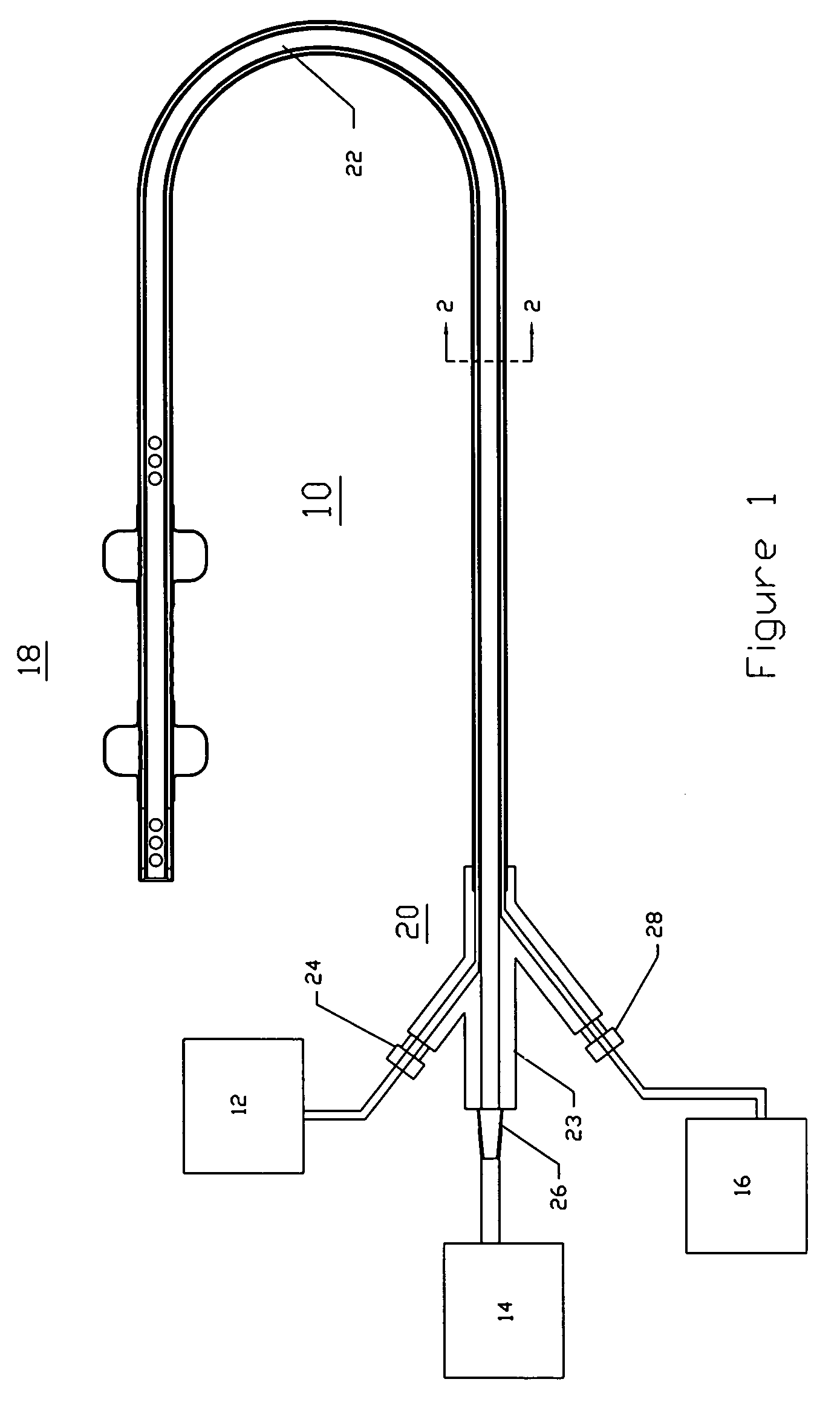
[0034]FIG. 1 illustrates a catheter, tube or cannula 10 of an embodiment of the invention connected to a cardioplegia infusion system or set 12, a venous drainage collection system 14 and an occlusion enabling system 16. In this preferred embodiment, the occlusion enabling system 16 is a balloon inflation system. The catheter 10 comprises a distal tip 18, a proximal end ...


PUM


Abstract

A system is disclosed for cannulating the vena cava of a patient during cardiopulmonary bypass procedures. Such cannulation is necessary for drainage of venous blood from the patient so that it may be oxygenated and pumped back to the patient to perfuse tissues during cardiac surgery and, more specifically, during periods of ischemic cardiac arrest or dysfunction. The device of the present invention not only provides venous drainage for cardiopulmonary bypass, but also performs the function of routing cardioplegic solution through the heart in the retrograde direction. Such cardioplegia provides protection to the heart during periods of ischemic cardiac arrest. This invention replaces a plurality of cannulae currently used for open-heart surgery, thus simplifying the surgical field and improving visibility of the heart. The device allows for the delivery of retrograde cardioplegia to the coronary circulation of both the right and the left side of the heart. The device further includes protection mechanisms to prevent overinflation or excessive pressurization of the right atrium during retrograde delivery of cardioplegia solution.

Description

PRIORITY CLAIM[0001]This application is a continuation of U.S. application Ser. No. 10 / 759,310, now U.S. Pat. No. 6,821,263, filed Jan. 16, 2004, which is a continuation-in-part of U.S. application Ser. No. 09 / 894,564, now U.S. Pat. No. 6,682,499, filed on Jun. 28, 2001, the entirety of which are hereby incorporated herein by reference.FIELD OF THE INVENTION[0002]The field of this invention is cardiac bypass surgery and cardiopulmonary bypass.BACKGROUND OF THE INVENTION[0003]During cardiac surgery for procedures such as coronary artery bypass grafting, heart valve repair or replacement, septal defect repair, pulmonary thrombectomy, atherectomy, aneurysm repair, aortic dissection repair and correction of congenital defects, cardiopulmonary bypass and cold cardiac ischemic arrest are often required. Typically, a cooled cardioplegia solution, a solution containing elevated levels of potassium, for example, is administered in the antegrade direction (in the direction of normal blood flo...

Claims


Application Information

Patent Timeline
Patent Type & Authority Patents(United States)
IPC IPC(8): A61M29/00A61M31/00A61M37/00A61M1/36
CPCA61M1/3653A61M1/3659A61M1/3613A61M1/3664A61M2202/047A61M2025/1013A61M1/3656A61M1/3623
Inventor LENKER, JAY A.
Owner INDIAN WELLS MEDICAL
Why Eureka
Try Eureka