Aircraft electronics cooling apparatus for an aircraft having a liquid cooling system

Inactive Publication Date: 2010-04-13
AIRBUS OPERATIONS GMBH
View PDF15 Cites 10 Cited by
  • Summary
  • Abstract
  • Description
  • Claims
  • Application Information

AI Technical Summary

Benefits of technology

[0012]The aircraft electronics cooling apparatus may include a heat exchanger of the first type through which flow the coolant of the liquid cooling system and air which is to be cooled by the coolant, the air to be cooled passing over the electronic device before it enters the heat exchanger of the first type. The air enters the aircraft electronics cooling apparatus, passes the electronic device to be cooled and is cooled in the heat exchanger. In some applications air at the usual cabin air temperature may be sufficient to cool the electronics of an aircraft. Cabin air flows through air inlets to the components, cooling them convectively, for example. The flow of ...

Problems solved by technology

However, the aircraft electronics cooling apparatus may also be so configured such that the coolant...

Method used


Image

  • Aircraft electronics cooling apparatus for an aircraft having a liquid cooling system
  • Aircraft electronics cooling apparatus for an aircraft having a liquid cooling system
  • Aircraft electronics cooling apparatus for an aircraft having a liquid cooling system

Examples


third embodiment

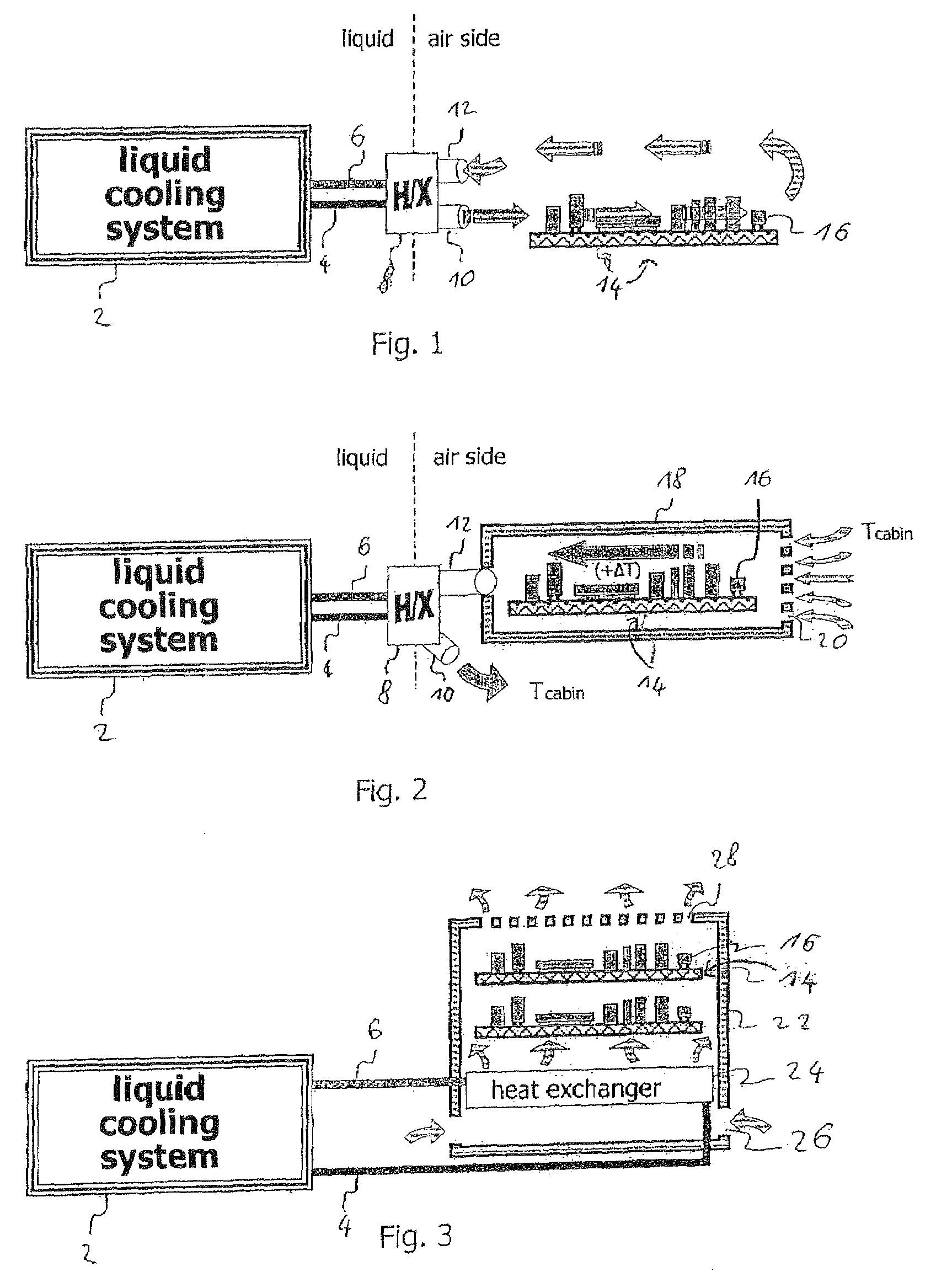
[0037]FIG. 3 shows the inventive aircraft electronics cooling apparatus. A plurality of electronic devices 14 with a plurality of electronic components 16 are arranged in a housing 22. At least one lower opening 26 is located in the lower region of the housing 22 and at least one upper opening 28 is located in the upper region of the housing 22. A heat exchanger 24 is arranged between the at least one lower opening 26 and the plurality of electronic devices 14. A liquid cooling system 2 supplies coolant to the heat exchanger 24 via a feed line 4, which coolant is returned to the liquid cooling system 2 via a return line 6. In this embodiment cooling takes place by free convection. The warm air with low density exits the housing 22 through the plurality of upper openings 28. At the same time air enters though the plurality of lower openings 26 of the housing 22, is cooled by the heat exchanger 24 and flows to the electronic devices 14 and their components 16 to be cooled.

fourth embodiment

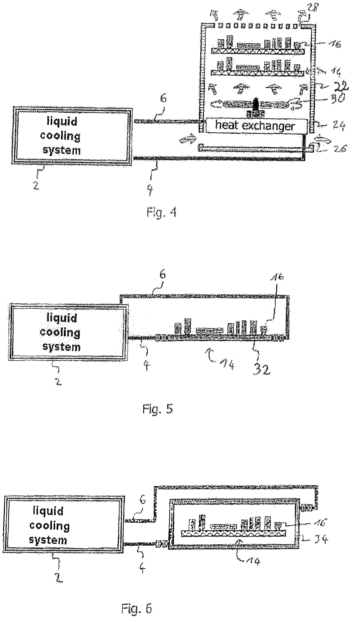
[0038]FIG. 4 shows the inventive aircraft air-conditioning system which is similar to the embodiment of FIG. 3 and additionally includes a fan 30 which is arranged in the housing 22 between the heat exchanger 24 and the plurality of electronic devices 14 with a plurality of components 14. The fan 30 generates an air flow which is directed towards the electronic devices 14 to be cooled. Air enters the housing via the plurality of lower openings 26, passes through the heat exchanger 24 and flows around the electronic devices 14 and their components 16 in order to cool same, and exits the housing 22 through the upper openings 28.

fifth embodiment

[0039]FIG. 5 shows the inventive aircraft electronics cooling apparatus. An electronic device 14 comprises a plurality of components 16 which are arranged on a board 32. The board 32 is in the form of a heat exchanger and coolant flows at least partially through said heat exchanger. A liquid cooling system 2 supplies coolant to the board 32 via a feed line 4, which coolant cools the components 16 arranged on the board 32. The coolant may also flow through at least one component 16 which is arranged on the board 32. The coolant exits the board into a return line 6 and is returned to the liquid cooling system 2.


PUM


Abstract

The invention relates to an improved aircraft electronics cooling system for an aircraft having a liquid cooling system (2), the aircraft electronics cooling system providing a thermal coupling between an electronic device (40a, 40b, 40c, 40d, 42, 44) to be cooled and the liquid cooling system (2) of the aircraft. A coolant delivered by the liquid cooling system (2) may flow through a board of the electronic device (40a, 40b, 40c, 40d), through a heat sink on which the electronic device (42) is arranged and/or through a housing in which the electronic device (44) is arranged. The coolant may be permanently in the liquid state in a cooling circuit. The coolant may vaporize at least partially while cooling the electronic device.

Description

BACKGROUND OF THE INVENTION[0001]Aircraft manufacturers and operators utilize a continuously increasing number of electronic assemblies in aircraft. The electronic assemblies enhance comfort in the cabin on the one hand and aircraft safety on the other. The electronic assemblies generate waste heat and must be cooled in order to function reliably. The air-conditioning apparatus of conventional aircraft are unable, or only partly able, to meet these additional cooling demands.[0002]In conventional, aircraft the electronic devices are so designed that either they must be cooled only by free convection, that is, an air flow is established only through density differences of the air and thus cools the components of the electronic device which are heating up, or additional fans which generate forced convention are provided. Additional cooling capacity for cooling the electronic devices can be made available at present only by an air-conditioning system and with the use of corresponding, ...

Claims


Application Information

Patent Timeline
IPC IPC(8): H05K7/20F28D15/00F28F27/00F28F7/00
CPCH05K7/20218H05K7/20681H05K7/20645
Inventor ULUC, OZANKIRYAMAN, AHMET KAYIHANFREY, ANDREAS
Owner AIRBUS OPERATIONS GMBH
Why Eureka
Try Eureka