Control system for internal combustion engine

a control system and internal combustion engine technology, applied in the direction of electrical control, process and machine control, instruments, etc., can solve the problems of known degraded ignition ability of fuel, and achieve the effect of stable ignitionability and improved ignition ability of fuel injected during the main injection

Active Publication Date: 2010-04-27
HONDA MOTOR CO LTD
View PDF11 Cites 9 Cited by
  • Summary
  • Abstract
  • Description
  • Claims
  • Application Information

AI Technical Summary

Benefits of technology

[0012]With the above-described structural configuration, the heat release amount in the predetermined crank angular range is calculated according to the detected pressure in the combustion chamber, and the amount of fuel injected during the first pilot injection of the plurality of pilot injections is controlled according to the calculated heat release amount. The heat release amount from the pilot injection occurring immediately before the main injection is detected by appropriately setting the predetermined crank angular range. Further, by controlling the fuel injection amount of the first-performed pilot injection according to the heat release amount, ignitionability of the fuel injected during the pilot injection immediately before the main injection is improved, and, consequently, ignitionability of the fuel injected during the main injection is also improved. Accordingly, stable ignitionability is obtained, especially in the low temperature condition, or the low load operating condition, of the engine.

Problems solved by technology

If similar control for a high load operating condition is attempted by the control system taught by JP '435, as in the low temperature condition or in the low load operating condition, the ignitionability of fuel is known to degrade.

Method used


Image

  • Control system for internal combustion engine
  • Control system for internal combustion engine
  • Control system for internal combustion engine

Examples


first embodiment

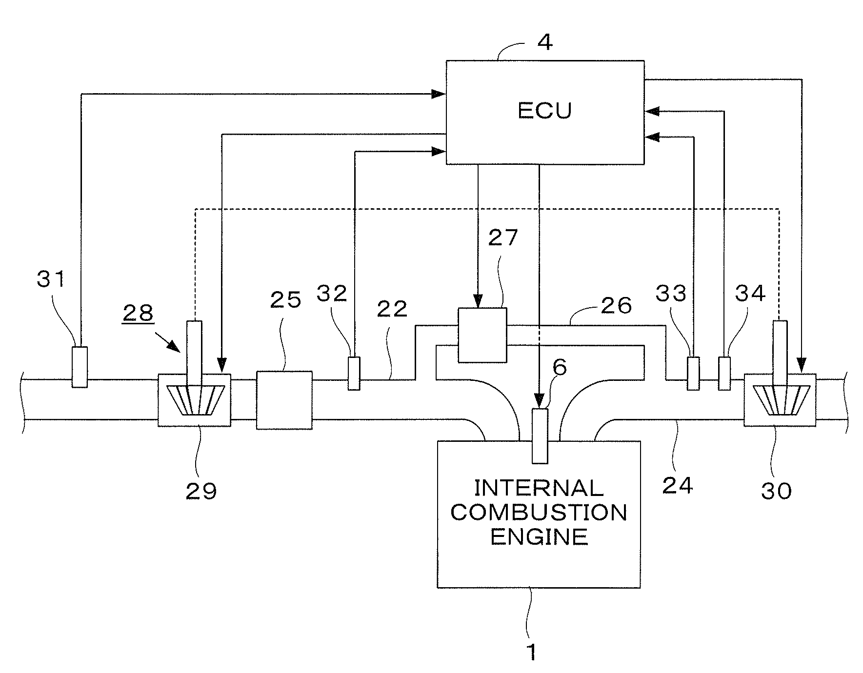
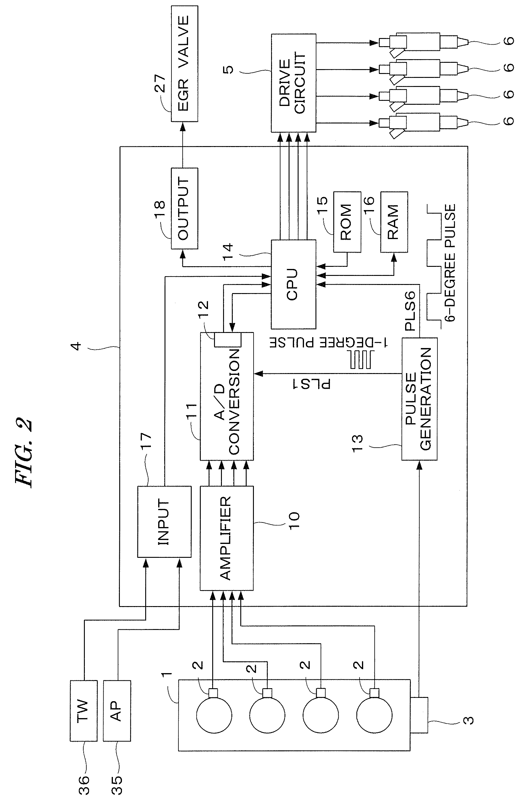
[0024]According to one embodiment of the present invention, FIGS. 1 and 2 are schematic diagrams of an internal combustion engine and a control system. The internal combustion engine 1 (hereinafter referred to as “engine”), has four cylinders and is a diesel engine, wherein fuel is injected directly into the cylinders. Each cylinder is provided with a fuel injection valve 6 electrically connected to an electronic control unit 4 (hereinafter referred to as “ECU 4”). The ECU 4 controls a valve opening period and a valve opening timing of each fuel injection valve 6.

[0025]The engine 1 has an intake pipe 22, an exhaust pipe 24, and a turbocharger 28. The turbocharger 28 includes a turbine 30 and a compressor 29. The turbine 30 is driven by the kinetic energy of exhaust gases. The compressor 29, which is rotationally driven by the turbine 30, compresses the intake air of the engine 1.

[0026]The turbine 30 has a plurality of movable vanes (not shown), and is configured so that the rotation...

second embodiment

[0066]In a second embodiment according to the present invention, a heat release amount in a predetermined crank angular range is calculated according to the detected cylinder pressure PCYL, and the fuel injection amount of the first pilot injection is controlled according to the calculated heat release amount when performing a plurality of pilot injections. The points in this embodiment, which are comparatively different from the first embodiment, will be described below.

[0067]As shown in FIG. 5, by adopting the double pilot injection mode, the compression end temperature TCMP is raised to improve the ignitionability of the fuel. Specifically, it is considered that the compression end temperature TCMP is raised by a combustion, or a low-temperature oxidation, of the fuel injected by the second pilot injection INJP2 to accelerate ignition of the fuel injected in the first pilot injection INJP1, which consequently improves ignitionability of the fuel injected by the main injection INJ...


PUM


Abstract

A control system for an internal combustion engine having at least one fuel injection valve for injecting fuel into a combustion chamber of the engine. A compression end temperature in the combustion chamber is estimated. A target compression end temperature is calculated according to an operating condition of the engine. A main injection and a plurality of pilot injections before the main injection are performed by at least one fuel injection valve. A fuel injection amount in a first-performed pilot injection of the plurality of pilot injections is controlled so that the estimated compression end temperature coincides with the target compression end temperature.

Description

BACKGROUND OF THE INVENTION[0001]1. Field of the Invention[0002]The present invention relates to a control system for an internal combustion engine in which compression ignition is performed, and particularly to a control system for controlling an amount of fuel injected during a pilot injection of fuel that is performed before a main injection of fuel.[0003]2. Description of the Related Art[0004]Japanese Patent Publication No. 3572435 (JP '435) discloses a control system for an internal combustion engine that estimates a compression end temperature that is a temperature of an air-fuel mixture in a cylinder when a piston is positioned at a compression top dead center. The control system disclosed by JP '435 increases the pilot injection amount of fuel when the estimated compression end temperature becomes relatively high. The control system of JP '435 suppresses a combustion noise by increasing the pilot injection amount of fuel in a high-load operating condition of an engine.[0005]...

Claims


Application Information

Patent Timeline
Patent Type & Authority Patents(United States)
IPC IPC(8): F02D41/30
CPCF02D35/023F02D35/026F02D41/403F02D41/064F02D2041/281F02D2250/18Y02T10/44F02D41/402Y02T10/40
Inventor HATANO, JUNICHIYAMAGUCHI, SATOSHIWADA, KATSUJITAKAHASHI, KENSUKE
Owner HONDA MOTOR CO LTD
Why Eureka
Try Eureka