Microfabricated fuel heating value monitoring device

a fuel heating value and microfabricated technology, applied in the field of heat measurement, can solve the problems of inability to meet the needs of certain end users, inability to accurately measure natural gas, and high cost of instrumentation for accurate natural gas analysis, and achieve the effect of prohibitively high cost of full gc instrumentation

Active Publication Date: 2010-05-04
NAT TECH & ENG SOLUTIONS OF SANDIA LLC
View PDF5 Cites 15 Cited by
  • Summary
  • Abstract
  • Description
  • Claims
  • Application Information

AI Technical Summary

Benefits of technology

[0013]The microfabricated fuel heating value monitoring device has applications in the natural gas industry where more information about gas content is needed and where the cost of full GC instrumentation is currently prohibitively high. Potenti

Problems solved by technology

When the fraction of heavier constituents is too high, it becomes unsuitable for certain end users.
Gas heating value and flow measurement errors on the order of a percent or less can have significant impacts to the industry in the areas of lost revenues and cash flow, since many pipeline networks possess gas transfer capacities that range from 0.5 to 1 billion cubic feet per day.
Because instrumentation for accurate natural gas analysis is expensive to purchase, operate and maintain, ubiquitous metering devices provide only volumetric measures of the quantity of natural gas consumed.
A further complication arises during gas transfers between wholesale or commercial entities along the gas supply chain when both gas volume and heating value indices can be used in the transaction.
Discrepancies between the two can result in billing errors or lost revenues.
Inaccuracies as high as 40° C. limit the ability to operate at the optimum firing temperature.
Controllers error on the side of safety to prevent part-life degradation from overfiring the turbines.
This method is highly accurate, but expensive in terms of equipment, maintenance, operation, and personnel.
Samples are often collected into bottles for once-a-month lab ana

Method used


Image

  • Microfabricated fuel heating value monitoring device
  • Microfabricated fuel heating value monitoring device
  • Microfabricated fuel heating value monitoring device

Examples


Embodiment Construction

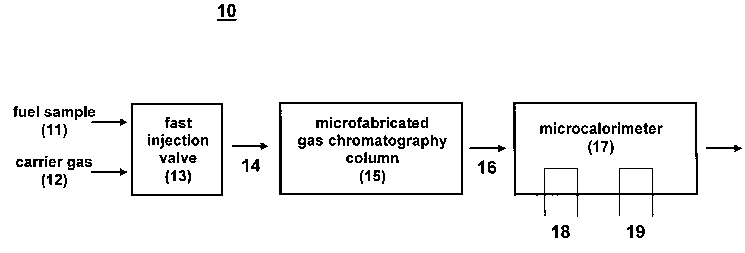
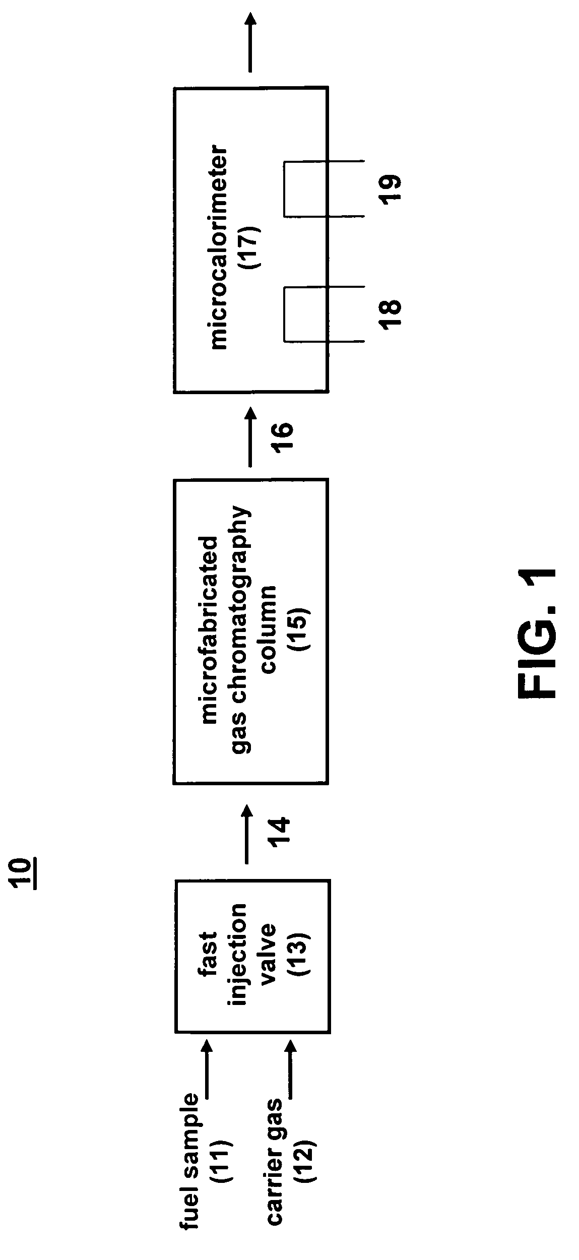
[0020]As shown in FIG. 1, the microfabricated fuel heating value monitoring device 10 of the present invention comprises a microfabricated GC column 15 in combination with a catalytic microcalorimeter 17. The GC column 15 and microcalorimeter 17 can be combined using either hybrid or monolithic methods. The microfabricated gas chromatography column comprises a channel formed in a substrate. To determine the heating value of a fuel sample 11, a small microliter volume 13 of the sample 11 is rapidly injected into the microfabricated GC column 15 using a fast injection valve 13. A carrier gas 12 pushes the fuel sample through the column 15, wherein constituents are separated as they traverse the length of the column. As the separated constituents 16 individually elute from the end of the column 15, they are quantitatively detected by the microcalorimeter 17. The microcalorimeter 17 comprises an active microhotplate 19, having a catalyst formed thereon, to record the combustion of the s...


PUM


Abstract

A microfabricated fuel heating value monitoring device comprises a microfabricated gas chromatography column in combination with a catalytic microcalorimeter. The microcalorimeter can comprise a reference thermal conductivity sensor to provide diagnostics and surety. Using microfabrication techniques, the device can be manufactured in production quantities at a low per-unit cost. The microfabricated fuel heating value monitoring device enables continuous calorimetric determination of the heating value of natural gas with a 1 minute analysis time and 1.5 minute cycle time using air as a carrier gas. This device has applications in remote natural gas mining stations, pipeline switching and metering stations, turbine generators, and other industrial user sites. For gas pipelines, the device can improve gas quality during transfer and blending, and provide accurate financial accounting. For industrial end users, the device can provide continuous feedback of physical gas properties to improve combustion efficiency during use.

Description

CROSS-REFERENCE TO RELATED APPLICATION[0001]This application claims the benefit of U.S. Provisional Application No. 60 / 688,878, filed Jun. 8, 2005, which is incorporated herein by reference.STATEMENT OF GOVERNMENT INTEREST[0002]This invention was made with Government support under contract no. DE-AC04-94AL85000 awarded by the U.S. Department of Energy to Sandia Corporation. The Government has certain rights in the invention.FIELD OF THE INVENTION[0003]The present invention relates to the measurement of the heat generated by combustion of a fuel and, in particular, to a microfabricated fuel heating value monitoring device that can be used for real-time monitoring of the heating value of natural gas.BACKGROUND OF THE INVENTION[0004]The natural gas industry and large volume consumers are seeking inexpensive methods for real-time monitoring of natural gas (NG) constituents. Such real-time monitoring is especially needed for pipeline switching and metering stations, turbine generators, a...

Claims


Application Information

Patent Timeline
IPC IPC(8): G01N25/20
CPCG01N33/225
Inventor ROBINSON, ALEX L.MANGINELL, RONALD P.MOORMAN, MATTHEW W.
Owner NAT TECH & ENG SOLUTIONS OF SANDIA LLC
Why Eureka
Try Eureka