Eureka AIR delivers breakthrough ideas for toughest innovation challenges, trusted by R&D personnel around the world.

All in one plan scan imaging for optimization of acquisition parameters

a scanning imaging and optimization technology, applied in the field of magnetic resonance imaging systems, can solve the problems of reducing the homogeneity of the rf transmitting field and thus the imaging quality, affecting the accuracy of the image, and the percentage of time spent calibrating versus clinical scanning time becoming too high, and achieving high resolution images

Inactive Publication Date: 2010-05-11
KONINKLIJKE PHILIPS ELECTRONICS NV
View PDF11 Cites 12 Cited by
  • Summary
  • Abstract
  • Description
  • Claims
  • Application Information

AI Technical Summary

Benefits of technology

The present invention provides a magnetic resonance imaging (MRI) system for acquiring high resolution images of a body. The system includes a means for acquiring a low resolution whole-body plan scan image of the body, a graphical user interface for identifying a region of interest in the plan scan image, and means for acquiring the high resolution image of the region of interest. The whole-body plan scan image is obtained by using a rapid imaging technique, such as the FFE technique, which allows for a quick scan of the body. The system can also use pattern recognition procedures to detect potential regions of interest in the plan scan image. The system can automatically position the region of interest to the region of optimum performance of the MRI system, which eliminates the need for manual positioning. The system can also extract body positioning parameters from the plan scan image, which can be used to determine the anatomy, geometry, orientation, and mass of the body inside the MRI system. The system can also perform an assignment between the region of interest and a part of the body, making it easier to identify specific body parts. Overall, the invention provides a more efficient and intuitive workflow for identifying and acquiring high resolution images of the body.

Problems solved by technology

Such a strong interaction not only degrades substantially the RF transmitting field homogeneity and thus the imaging quality, but also can cause concerns about the safety because the electric field associated with the RF transmitting magnetic field increases with the inhomogeneity of the RF transmitting field.
When for example a plurality of specific calibrations has to be performed sequentially, the percentage of time spent calibrating versus clinical scanning time would become too high.
Consequently scanning sessions dramatically expand in time and increase in complexity for the patient and the operator alike.

Method used


Image

  • All in one plan scan imaging for optimization of acquisition parameters
  • All in one plan scan imaging for optimization of acquisition parameters
  • All in one plan scan imaging for optimization of acquisition parameters

Examples


Embodiment Construction

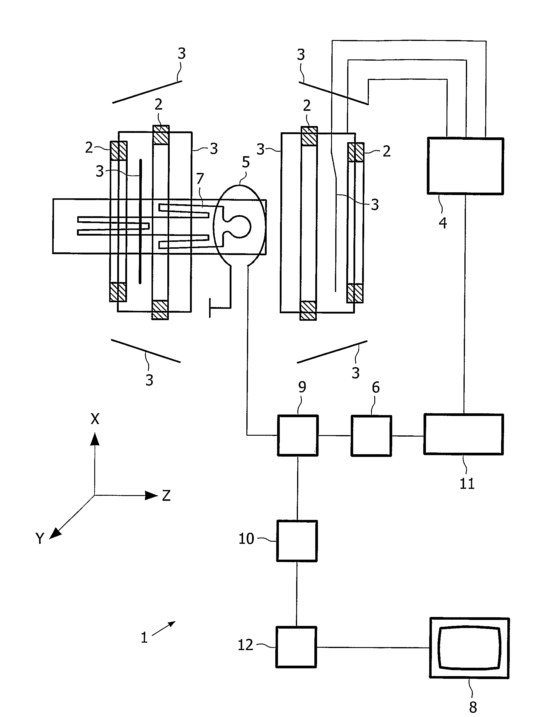
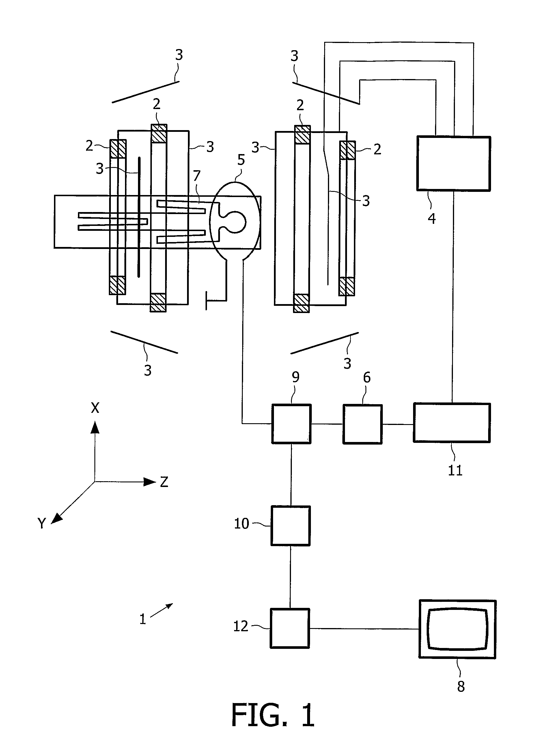
[0043]FIG. 1 shows a magnetic resonance imaging system 1 which includes a main magnet system 2 for generating a steady magnetic field, and also several gradient coils providing a gradient coil system 3 for generating additional magnetic fields having a gradient in the X, Y, Z directions. The Z direction of the coordinate system shown corresponds to the direction of the steady magnetic field in the main magnet system 2 by convention. The Z axis is an axis coaxial with the axis of a bore hole of the main magnet system 2, whereby the X axis is the vertical axis extending from the center of the magnetic field, and whereby the Y axis is the corresponding horizontal axis orthogonal to the Z axis and the X axis.

[0044]The gradient coils of the gradient coil system 3 are fed by a power supply unit 4. An RF transmitter coil 5 serves to generate RF magnetic fields and is connected to an RF transmitter and modulator 6.

[0045]A receiver coil is used to receive the magnetic resonance signal genera...


PUM


Abstract

The present invention provides a magnetic resonance imaging system making use of low resolution, whole-body plan scan image of a body. The whole-body plan scan image is exploited to gather a plurality of individual information of a body that is essential for an optimization of acquisition parameter for acquisition of a high resolution and high quality image of a region of interest of the body. Moreover, the whole-body plan scan image is used in order to facility a determination and a selection of a region of interest to be performed by an operator. Additionally, the MRI provides effective means for autonomously identifying specific body parts or even organs of a patient. Providing the entire information that can be extracted from the whole-body plan scan image to the operator effectively simplifies the workflow of the operator in an intuitive way. Preferably, during acquisition of the low resolution whole-body plan scan image, necessary calibration parameters for acquisition of the final high resolution image are obtained.

Description

FIELD OF THE INVENTION[0001]The present invention relates to the field of magnetic resonance imaging systems.BACKGROUND AND PRIOR ART[0002]Improving the image quality of a magnetic resonance imaging system, i.e. improving signal to noise ratio (SNR) and resolution of images, can in principle be achieved by increasing the magnitude of the static magnetic field as well as realizing a faster gradient switching. In order to enhance the SNR, magnetic resonance imaging (MRI) systems using a high static magnetic field have been developed. However, as the strength of the static magnetic field increases, the frequency of the RF transmitting field linearly increases as well.[0003]Increasing the static magnetic field for example from 1.5T to 3T results in a RF transmitting field whose interaction with a human body can no longer be neglected. Interaction between the RF transmitting field and the human body is observed by, for example, the dielectric resonance effect, since the effective wavelen...

Claims


Application Information

Patent Timeline
Patent Type & Authority Patents(United States)
IPC IPC(8): A61B5/05G01V3/00G01R33/20G01R33/56
CPCG01R33/543G01R33/546G01R33/56375
Inventor HARVEY, PAUL ROYSTONKRUGER, LUC RICHARDSLEGT, SANDER
Owner KONINKLIJKE PHILIPS ELECTRONICS NV
Why Eureka
Eureka Blog
Learn More