Non-contact thermo-elastic property measurement and imaging system for quantitative nondestructive evaluation of materials

a non-contact, thermo-elastic property technology, applied in the direction of instruments, specific gravity measurement, optical radiation measurement, etc., can solve the problems of significant change in the elastic modulus, non-destructive techniques, dramatic deformation of the strength of materials exposed to heat, etc., to increase the energy level of subsequent pulses

Active Publication Date: 2010-05-18
UNIV OF DAYTON
View PDF28 Cites 22 Cited by
  • Summary
  • Abstract
  • Description
  • Claims
  • Application Information

AI Technical Summary

Benefits of technology

[0011]In one embodiment, a non-contact thermo-elastic imaging system for detecting defects in a structure is disclosed. The system comprises a sound source directing at least one pulse of a sound signal at a first energy level at the structure for a predetermined period of time. A thermal camera is directed towards the structure and generating thermal images of the structure when the sound source emits the at least one pulse of the sound signal. The system includes a controller coupled to the sound source and the thermal camera. The controller provides timing signals therebetween, and increases energy levels of subsequent pulses the sound pulses.
[0014]Although not limited to, the following are some noted advantages of the present invention. The concept of relating the thermo elastic parameter to heat damage and its measurements are based on thermodynamics of materials. The instrumentation provides a non-contact nondestructive technique to detect, image and quantitatively measure the heat damage in organic matrix composites.

Problems solved by technology

While the polymer composites provide excellent strength / weight ratio, their strength degrades dramatically when exposed to heat.
On an aircraft, this could happen due to fire accidents or accidental exposure to excessive heat during repair or due to heat generation due to lightening strike.
Some of these techniques are nondestructive in nature and some are destructive.
While destructive techniques essentially attempt to measure the loss of mechanical strength in the composite, nondestructive evaluation (NDE) techniques attempt to relate the measured property to the loss of strength.
However, significant change in the elastic modulus occurs only when gross damage occurs in the material.
Accordingly, prior art NDE techniques are not sensitive to detecting “incipient” damage in composites which is responsible for the loss of physical or mechanical properties without gross changes in structure such as cracking, blistering or delamination.
However, it has been observed that significant changes in thermal properties occur only when the composite has undergone gross damage.
Changes in thermal properties during early stages of heat damage in composites are quite small and hence the IR thermography is not a sensitive method.
However, this contact technique of exciting the structure with high amplitude ultrasonic waves raises concerns about the damage that could be introduced due to excitation process via direct contact between the composite and the acoustic horn.
The acoustic horn in contact when excited operates like a hammer and may cause damage to the specimen.
In addition, the relation between the temperature changes and the amount of heat damage is complicated by excitation of many different modes of vibration in the structure due to direct contact between the horn and specimen.
Accordingly, it is to be appreciated that while many NDE techniques have been used in the past for evaluation of heat damage in composites, most of them have limited success and capable of revealing gross damage only.

Method used


Image

  • Non-contact thermo-elastic property measurement and imaging system for quantitative nondestructive evaluation of materials
  • Non-contact thermo-elastic property measurement and imaging system for quantitative nondestructive evaluation of materials
  • Non-contact thermo-elastic property measurement and imaging system for quantitative nondestructive evaluation of materials

Examples


Embodiment Construction

[0021]The following description of the embodiments of the invention directed to a non-contact nondestructive evaluation system and method thereof for testing and evaluation of a material based on measuring and imaging heat generation and increase of temperature due to interaction of acoustic waves with the material is merely exemplary in nature, and is in no way intended to limit the invention or its applications or uses.

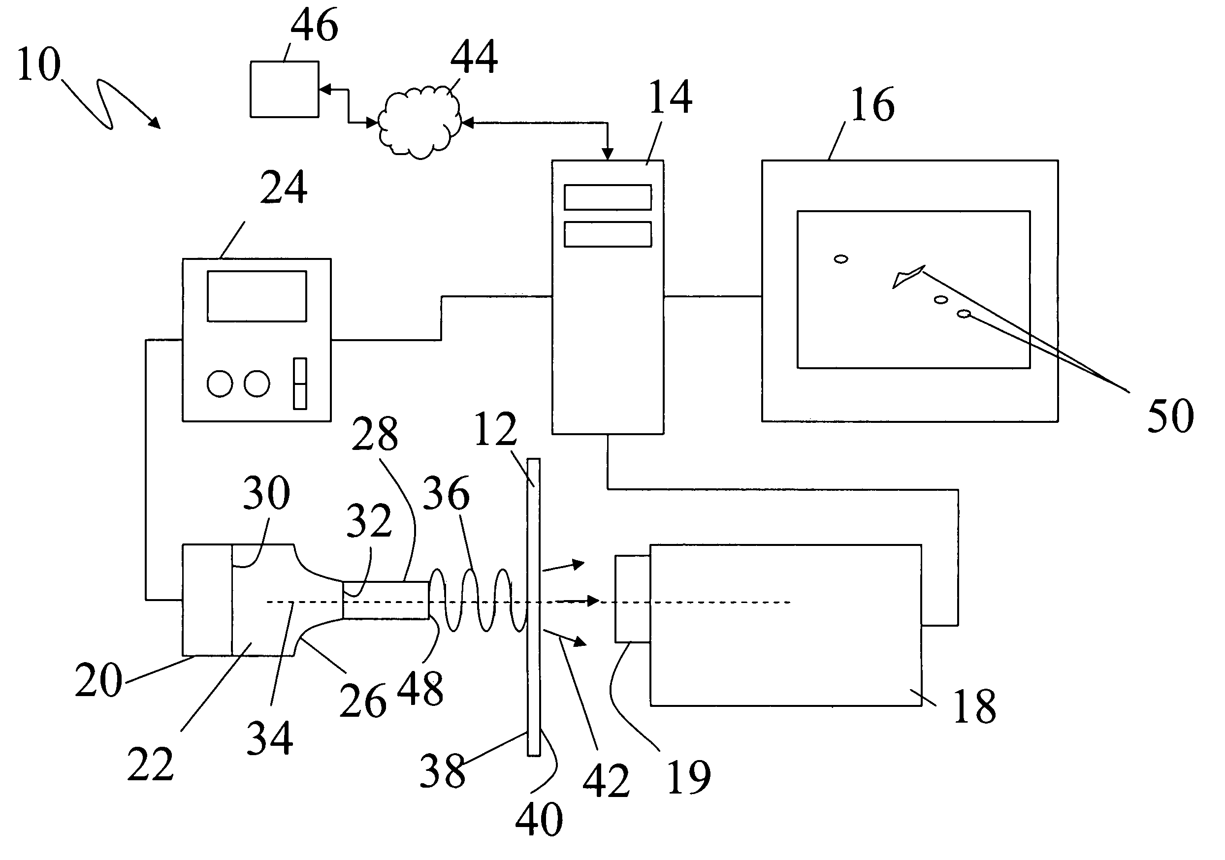
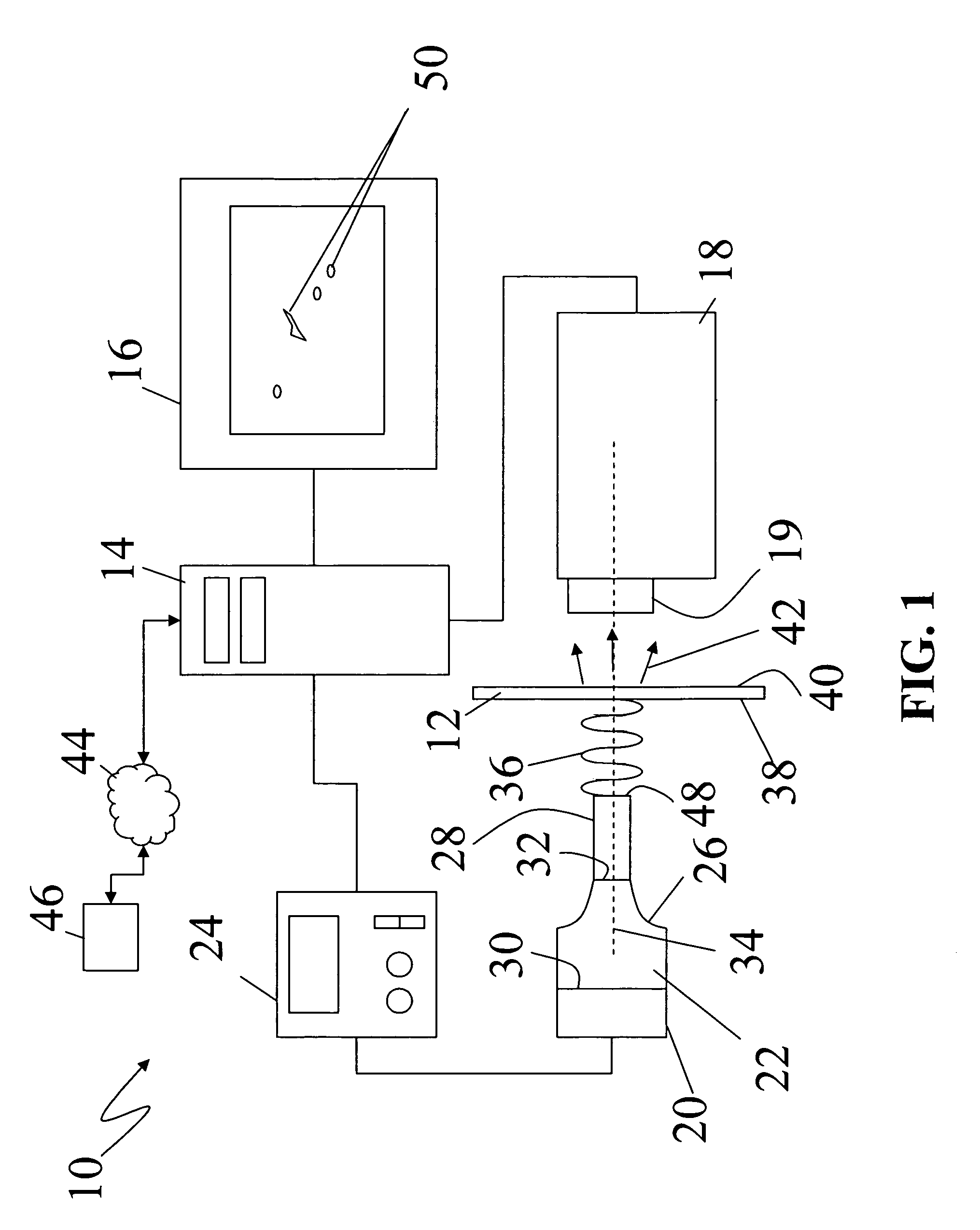
[0022]The basic principles of the methodology and the block diagram of a non-contact thermo-elastic property measurement and imaging system 10 are shown in FIG. 1, according to an embodiment of the present invention. The system 10 is being used to detect defects, such as cracks, corrosion, delaminations, disbonds, etc., in a specimen 12. The specimen 12 is intended to represent any structural component or material, such as an aircraft skin, turbine blades, structural welds, that may include these types of defects. It is stressed that the specimen 12 does not need to...


PUM

PropertyMeasurementUnit
frequencyaaaaaaaaaa
frequencyaaaaaaaaaa
diameteraaaaaaaaaa

Abstract

A non-contact thermo-elastic property measurement and imaging system and method thereof are described. Acoustic energy is incident on a first surface of a specimen under test. The acoustic energy is converted partially into heat by the specimen, causing a slight increase in the temperature in a region of interaction. The temperature increase is imaged using a high sensitivity infrared camera. Presence of defects (surface and subsurface) in the material modifies the distribution of temperature. An image of temperature distribution can be used for nondestructive testing and evaluation of materials. The temperature change in the specimen caused by acoustic excitation is related to thermal and elastic properties of the material. A measurement of the change in the temperature as a function of the amplitude of incident excitation can be used for direct measurement of thermo-elastic property of the specimen.

Description

STATEMENT OF GOVERNMENT INTEREST[0001]The invention described herein may be manufactured and used by and for the Government of the United States of America for Governmental purposes without the payment of any royalties thereon or thereto.FIELD OF THE INVENTION[0002]This invention relates generally to a system and method for the detection of defects in a material and, more particularly, to a non-contact thermo-elastic property measurement and imaging system for quantitative nondestructive evaluation of materials.BACKGROUND OF THE INVENTION[0003]Varieties of organic composites are in use for their superior strength and low density compared to metallic structures. These organic composites consist of fibers embedded in polymer matrices. Many layers are superposed on each other to obtain high strength and superior properties. For several decades, the aerospace industries have taken the advantage of superior physical properties and weight of the composite materials. Generally, composites ...

Claims


Application Information

Patent Timeline
Patent Type & Authority Patents(United States)
IPC IPC(8): G01N29/04G01J5/02G01N25/00
CPCG01N25/72G01N2291/0231G01N2291/0421G01N2291/02827G01N2291/02881G01N2291/0258
Inventor SATHISH, SHAMACHARYREIBEL, RICHARDWELTER, JOHN T.BUYNAK, CHARLES
Owner UNIV OF DAYTON
Why Eureka
Try Eureka