
Eureka
For R&D, Eureka makes reading and utilizing patents & technical documents easy.
Eureka AIR
Designed for self-driven R&D workflows. Generate viable solutions, solve complex R&D challenges, empower your innovation with AI.

Eureka Materials
Designed for material experts only. Revolutionize your material R&D, from search, analyze, to developing new materials.

TechResearch
Generate reliable direction feasibility study reports for your R&D in just a few steps.

TechSeek
Discover and master advanced knowledge NOW. Basics, ideas, possibilities, all at once.

TechMind
As an expert in R&D Theories, TechMind can generates customized viable solutions instantly.

TechRisk
Analyze your overall solution with one click, know your potential R&D risks in advance.

TechMonitor
Get weekly tech updates, stay abreast of the latest tech innovations and key insights.
Self-interfering tomography system
- Summary
- Abstract
- Description
- Claims
- Application Information
AI Technical Summary
Benefits of technology
Problems solved by technology
Method used
Image

Examples
Embodiment Construction
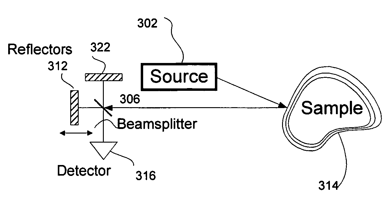
[0031]The optical system of one embodiment of the invention is schematically presented in FIG. 3A. A low coherence light source 302 emits optical radiation with a short coherence length and this is directed, either directly or via a fiber or other light guide, to illuminate a sample 314, such as tissue or an object that is to be imaged. Radiation re-emitted and collected from the sample 314 is divided by a beam splitter 306 into two signals, directed along two optical paths. Each of these radiation beams propagates to a corresponding optical path reflector, 312 or 322, respectively, which reflects the radiation back to the divider 306 and to a detector 316 that is positioned to receive the radiation. The output signal of the detector represents the structure of the sample and is processed to develop an image. One of the optical path reflectors can be moving so that it creates a variable optical delay; this has the effect, in subsequent signal processing, of scanning the sample depth...
PUM
 Abstract
Description
Claims
Application Information
 - R&D Engineer
- R&D Manager
- IP Professional
- Industry Leading Data Capabilities
- Powerful AI technology
- Patent DNA Extraction
Browse by: Latest US Patents, China's latest patents, Technical Efficacy Thesaurus, Application Domain, Technology Topic, Popular Technical Reports.
© 2024 PatSnap. All rights reserved.Legal|Privacy policy|Modern Slavery Act Transparency Statement|Sitemap|About US| Contact US: help@patsnap.com