IPM motor system and control method thereof

a technology of internal permanent magnet and motor system, which is applied in the direction of motor/generator/converter stopper, dynamo-electric converter control, dynamo-electric gear control, etc., can solve the problems of fitting one, limited kind of it, and high cost of position data and encoder having a z phase, and achieve high drive efficiency

Inactive Publication Date: 2010-06-08
NIPPON YUSOKI
View PDF12 Cites 59 Cited by
  • Summary
  • Abstract
  • Description
  • Claims
  • Application Information

AI Technical Summary

Benefits of technology

[0017]An object of the present invention is to provide an IPM (Interior Permanent Magnet) motor system which is cheap and has a high drive efficiency and a control method of an IPM motor.

Problems solved by technology

The resolver to obtain position data and the encoder having a Z phase are expensive, and a kind of it is limited, and there is no fitting one depending on an axis diameter.
Therefore, a calculation amount increases and practical use is difficult.
A calculation amount is more, and practical use is difficult in point of responsibility and reliability.
A rotor position detection error by the position detecting device causes a torque error in the motor.
(1) estimation error of a rotor initial position,
(2) lack of a pulse resolution,
(3) delay of detection in hardware and delay of speed calculation in software,
On the other hand, in the IPM motor, a resolver is mainly used to acquire correct position data but the resolver is expensive.

Method used


Image

  • IPM motor system and control method thereof
  • IPM motor system and control method thereof
  • IPM motor system and control method thereof

Examples


Embodiment Construction

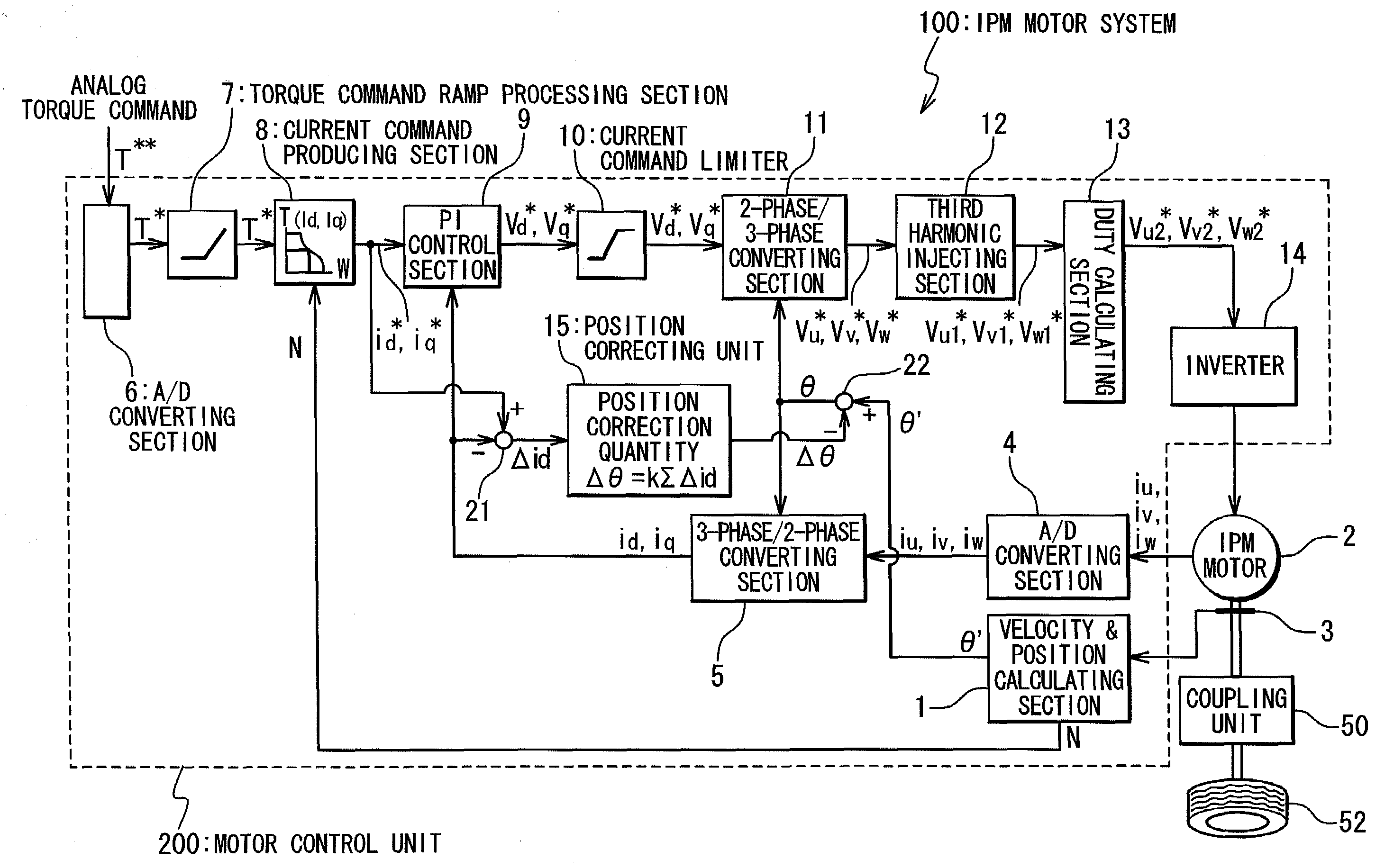
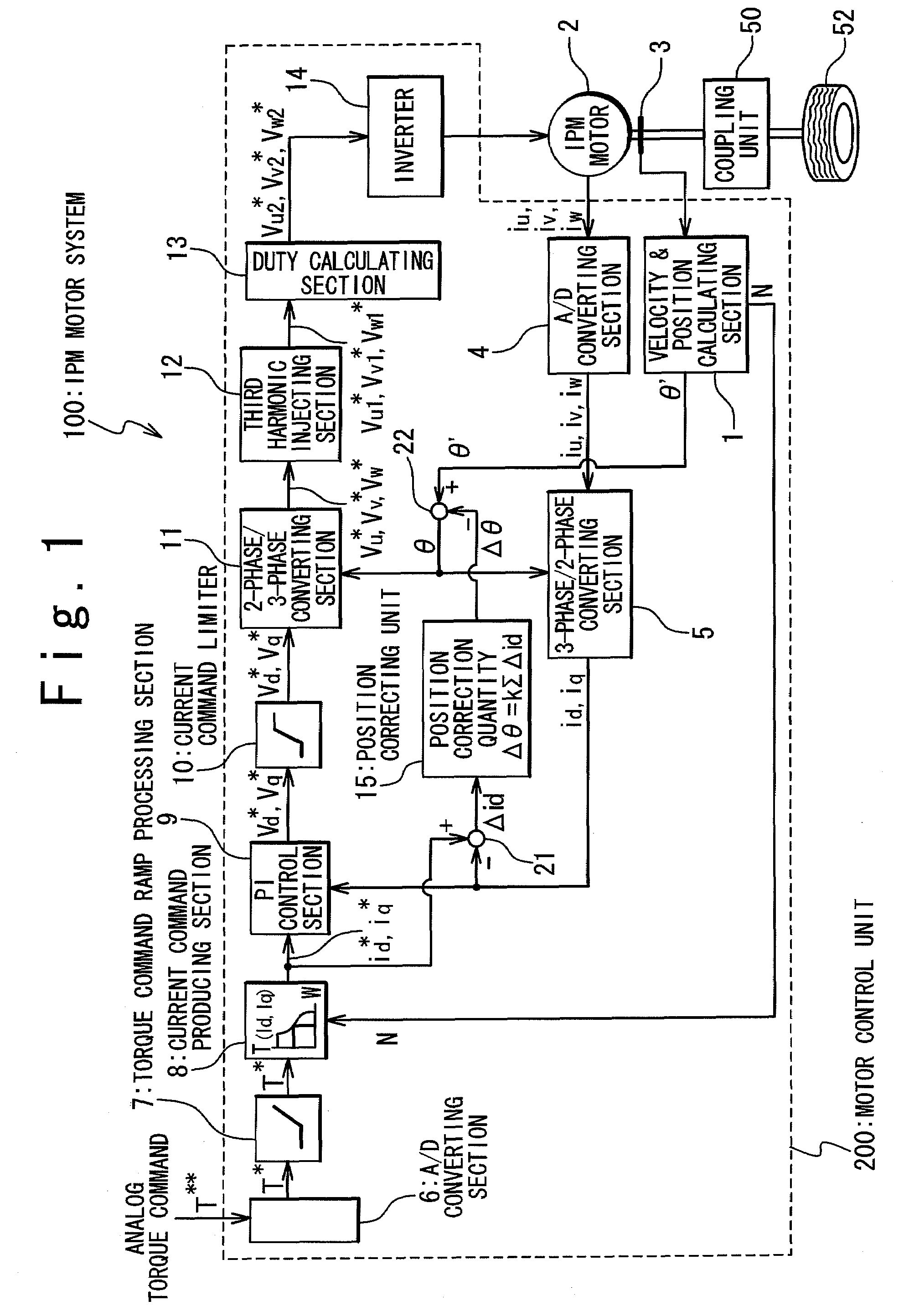
[0034]Hereinafter, an IPM motor system according to the present invention will be described in detail with reference to the attached drawings.

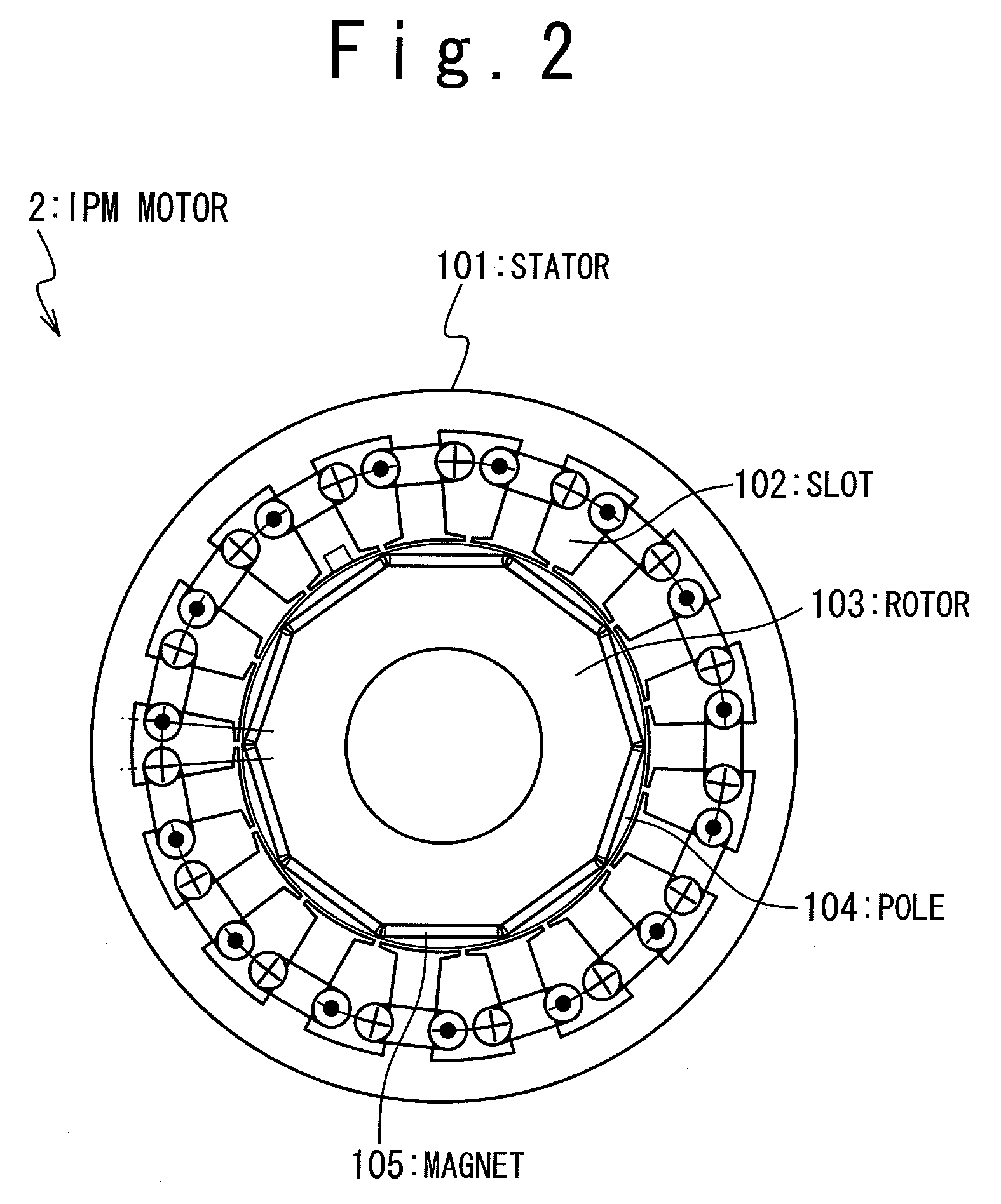
[0035]The IPM motor system of the present invention is composed of an IPM motor of a stator having slots and a rotor having poles, and a motor control system which drives and controls the rotor to the stator. A cheap bearing sensor is used for the detection of an angle position of the rotor. An estimation precision of an initial angle position of the rotor to the stator is selected to be equal to an angle unit precision of a stable position of the rotor to the stator which causes based on a combination of the number of poles and the number of slots. By this, the motor control system acquires angle position data of the rotor in a high precision and can carry out the position control of the rotor. Moreover, when an external torque is loaded to the rotor, a correction value of the angle position of the rotor based on the magnitude of the external...


PUM


Abstract

An IPM (Interior Permanent Magnet) motor system is provided with an IPM motor provided with a stator having slots and a rotor having poles, and a control unit which controls the rotor to the stator. An estimation precision of an initial angle position of the rotor to the stator is selected such that it is substantially the same as an angle unit precision of stable positions of the rotor to the stator which is based on a combination of the number of poles and the number of slots. In this way, the cheap IPM motor system with a high drive efficiency and a control method of the IPM motor system are provided.

Description

RELATED APPLICATIONS[0001]The present application is based on International Application No. PCT / JP2006 / 303259, filed Feb. 23, 2006, and claims priority from, Japanese Application No. 2005-049633, filed Feb. 24, 2005, the disclosure of which is hereby incorporated by reference herein in its entirety.TECHNICAL FIELD[0002]This invention is related to an IPM (Interior Permanent Magnet) motor system and a control method thereof.BACKGROUND ART[0003]An electric driving system of a hydraulic pressure pump and a wheel driver is developed, and AC motors are extensively used to accomplish higher efficiency than a DC motor. Of the AC motors, especially, an IPM motor has a high drive efficiency and also is excellent in responsibility. For this reason, the IPM motor has been extensively used in recent years. For control of the IPM motor, correct position data of a rotor is necessary, unlike the conventional DC motor and AC motor (induction motor).[0004]The following position detecting devices are...

Claims


Application Information

Patent Timeline
Patent Type & Authority Patents(United States)
IPC IPC(8): H02P6/08
CPCB60L11/1864B60L15/025H02P29/0038B60L2220/12B60L2220/14B60L2200/26Y02T10/643Y02T10/7005Y02T10/7061B60L2220/18B60L58/21H02P29/50Y02T10/64Y02T10/70
Inventor NAKAMURA, MITSUGUISOBE, SHINICHISAKURAI, TAKAOSHIRASU, TAKAYA
Owner NIPPON YUSOKI
Why Eureka
Try Eureka