
Device for guiding and tensioning supply lines

a supply line and cable technology, applied in the direction of drilling machines, drilling apparatus, pipe supports, etc., can solve the problems of the tackle being susceptible to failure, and achieve the effect of ensuring the stability of the tension roller

Inactive Publication Date: 2010-06-15
WIMMER ALOIS
View PDF13 Cites 0 Cited by
  • Summary
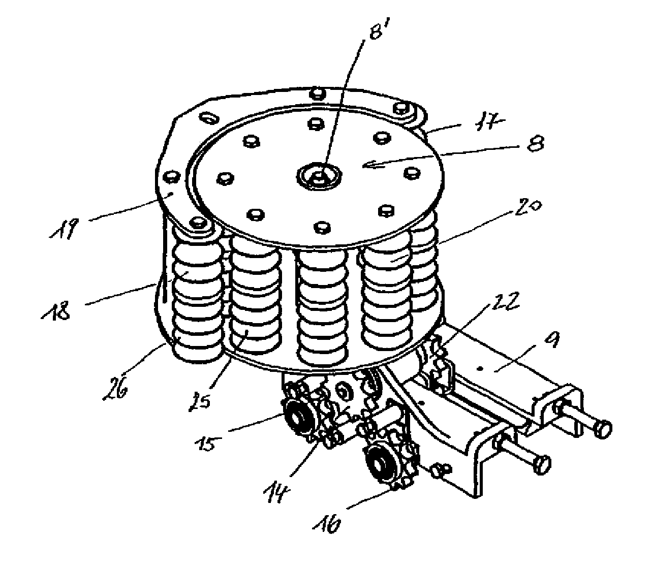
  • Abstract
  • Description
  • Claims
  • Application Information

AI Technical Summary

Benefits of technology

[0004]The invention is based on the object to provide a device of the afore-stated type, by which the tension roller can be actively controlled for movement in both directions, wherein the drive should be arranged in a substantially protected environment and should be less prone to fail.
[0005]This object is attained in accordance with the present invention by mounting a further transport wheel for advancing the tension roller onto the shaft of the pinion that engages the transport chain, for interaction with a fixed chain, rack, fixed traction rope, or the like. As a result, the tension roller is forced to synchronously move along the guide for the working tool, with this type of drive being less prone to fail.
[0006]The fixed chain, rack, fixed traction rope, or the like, may advantageously be mounted elastically yielding in the advance direction so that changes as a result of wear or heat expansion or the like can be compensated. The tension roller may hereby be rotatably supported on a carriage which also rotatably supports the shaft with the pinion and the transport wheel, wherein deflection rollers are supported on the carriage in a same plane as the transport wheel for respectively guiding the fixed chain or the fixed traction rope upstream and downstream of the transport wheel. This ensures a continuously reliable engagement and reliable looping of the transport wheel by the fixed chain or the fixed traction rope.
[0007]In order to keep the rolling resistance along the tension roller as low as possible, the tension roller in a manner known per se may be formed by several rolls which are arranged along a circle defined by a center point coinciding with the axis of the tension roller and which are defined by rotation axes in parallel relationship to the rotation axis of the tension roller, wherein counter rolls may be associated to the outer circumference of the tension roller and the rolls. As a result, the supply lines or the supply hoses bear only along the rollers upon the tension roller, wherein the rolls as a consequence of their rotatability compensate the rolling resistance or a possible relative movement between tension roller and supply hoses, wherein a detachment of the supply lines from the tension roller or the rolls of the tension roller is prevented. In addition, the tension roller or rolls and / or counter rolls may be provided on the outer surface area with wrap-around grooves for the at least partial acceptance of the supply lines, thus also preventing a lateral dislocation of the supply lines on the tension roller.

Problems solved by technology

The drawback of such a design is the susceptibility of tackles to fail, in particular when subjected to rough handling in the area of such tools.

Method used


Image

  • Device for guiding and tensioning supply lines
  • Device for guiding and tensioning supply lines
  • Device for guiding and tensioning supply lines

Examples


Embodiment Construction

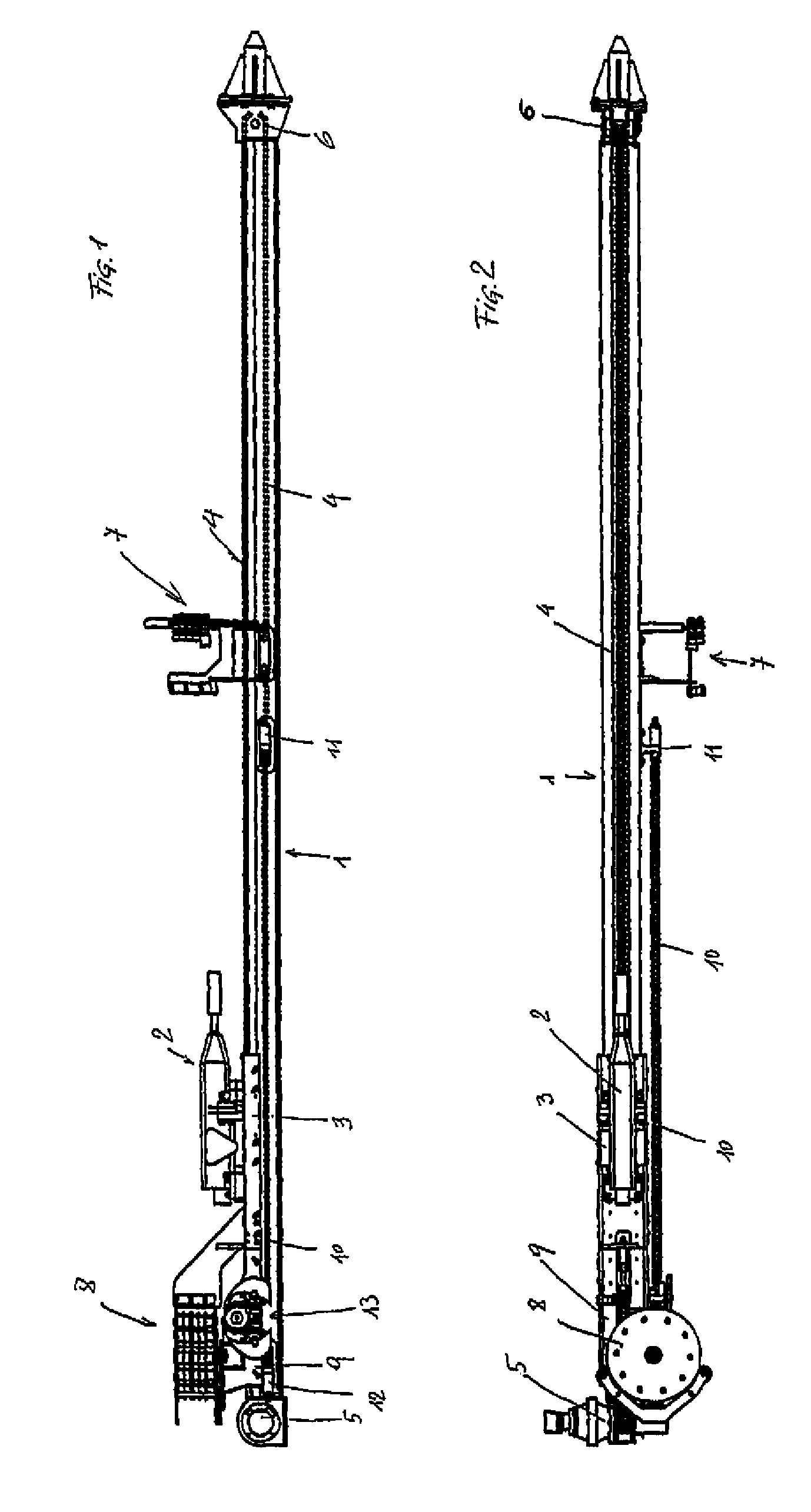
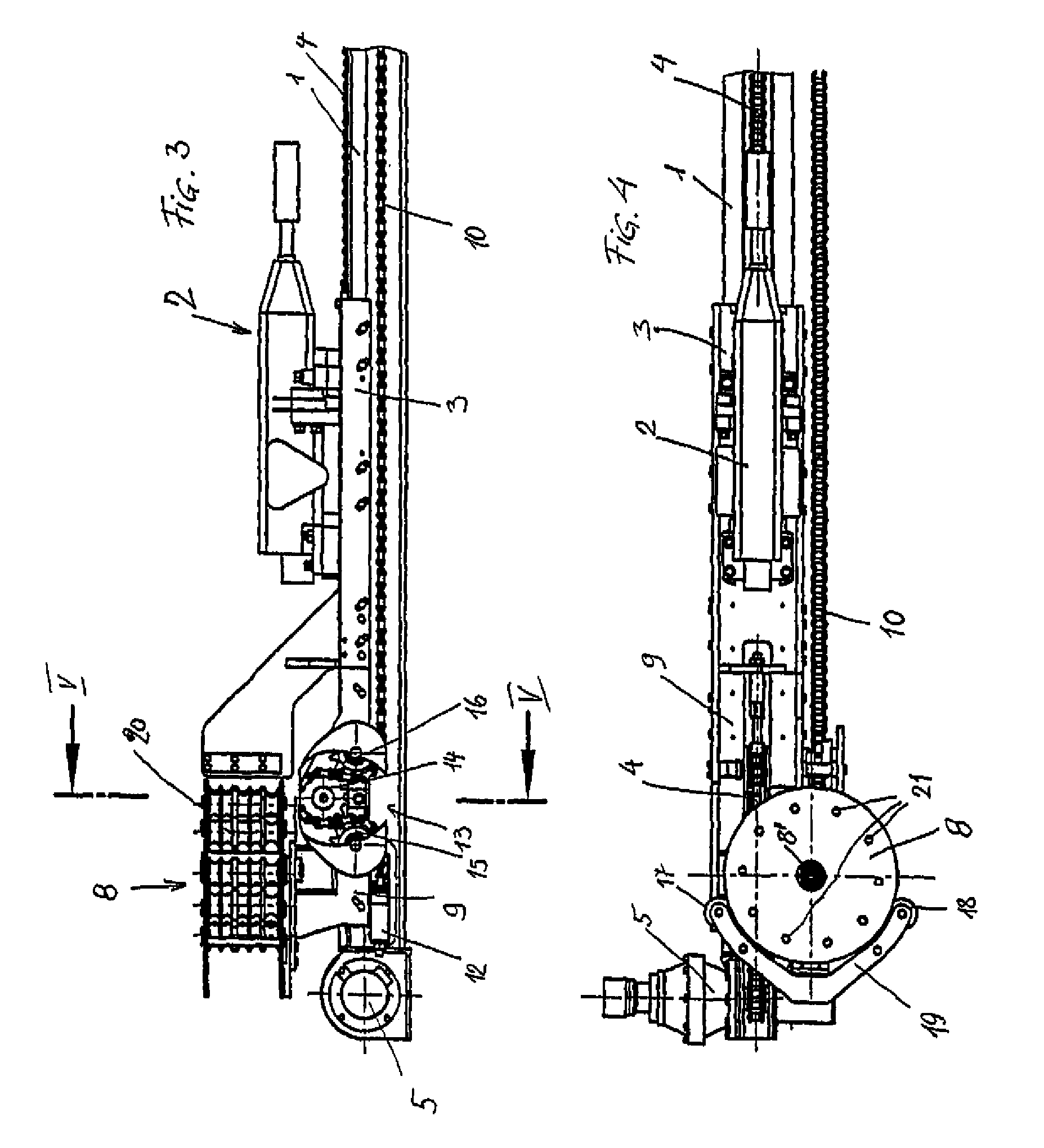
[0018]1 designates a guide along which the working tool 2 is movable via a carriage 3. This movement is realized by a transport chain 4 which is configured as a revolving chain having ends secured to the carriage 3. This revolving transport chain is looped about a drive 5 with a pinion and a deflection roller 6. The guide 1 can be attached to an excavator arm via a conventional suspension.

[0019]Provided between a mounting 7 and the working tool 2 are supply lines which are not shown here and provided for supply of hydraulic liquid, energy, and the like to the working tool. Control lines may also be provided between the mounting 7 and the working tool 2. Provided on this mounting are the supply feeds from the excavator after attachment to an excavator boom. These lines are prevented from sagging by a tension roller 8 about which the supply lines are routed. As the tension roller 8 acts like a loose pulley on a tackle, when the working tool advances, it must be moved in synchronism wi...


PUM


Abstract

In a device for guiding and tensioning supply lines for working tools movable along a straight guide, e.g. supply lines of a hydraulic hammer drill on an advance mounting, the advance of the working tool is implemented by means of a revolving transport chain driven by a sprocket wheel, and the supply line(s) are guided between the connections on the fixed guide and the connections on the working tool by a tension roller which causes a deflection about 180° and is movable in advance direction downstream the working tool conjointly therewith in the same direction but at half the advance speed, wherein the tension roller is slidably guided on the guide for the working tool transversely to its rotation axis, and wherein a pinion engages the transport chain for driving the movement of the tension roller and interacts with a fixed chain on the opposite side. To realize a controlled movement of the tension roller in both direction, a further transport wheel (14) for the advancement of the tension roller (8) is mounted onto the shaft (23) of the pinion (22) that engages the transport chain (4), for interaction with a fixed chain, a rack, a fixed traction rope, or the like.

Description

BACKGROUND OF THE INVENTION[0001]The invention relates to a device for guiding and tensioning supply lines for working tools movable along a straight guide, e.g. supply lines of a hydraulic hammer drill on an advance mounting, wherein the advance of the working tool is implemented by means of a revolving transport chain driven by a sprocket wheel, and the supply line(s) are guided between the connections on the fixed guide and the connections on the working tool via a tension roller which causes a deflection by about 180° and is movable in advance direction downstream the working tool conjointly therewith in the same direction but at half the advance speed, wherein the tension roller is slidably guided transversely to its rotation axis on the guide for the working tool, and wherein the drive for the movement of the tension roller includes a pinion which engages the transport chain and interacts with a fixed chain on the opposite side.[0002]According to a known design, the tension ro...

Claims


Application Information

Patent Timeline
Patent Type & Authority Patents(United States)
IPC IPC(8): B23Q5/02E21B19/084F16L3/02
CPCE21B19/084E21B19/08
Inventor WIMMER, ALOIS
Owner WIMMER ALOIS
Learn More