Apparatus, method and system for handling, positioning, and/or automatically orienting objects

a technology of objects and apparatuses, applied in the field of automatic positioning and/or orienting objects, can solve the problems of increasing complexity of systems, difficult calibration, expensive, time-consuming and reducing throughput,

Inactive Publication Date: 2010-06-15
PIONEER HI BRED INT INC
View PDF20 Cites 27 Cited by
  • Summary
  • Abstract
  • Description
  • Claims
  • Application Information

AI Technical Summary

Benefits of technology

[0015]c. can handle relatively large quantities of objects efficiently and economically;
[0016]d. can have substantial flexibility with respect to needed functions and applications;

Problems solved by technology

Some more complex systems even use such things as artificial or machine vision and sort on the basis of color or physical characteristics from image analysis.
Sorting or discriminating between objects involves certain technological and practical issues.
Automatic handling and positioning of relatively small objects can include similar or additional issues.
Difficulties in automatic orientation of objects in automatic assembly processes have been widely discussed.
As can be appreciated, such systems can be quite complex, expensive, and difficult to calibrate.
These systems also require each part to be individually handled by the robot, which can be time-consuming and reduce throughput.
It also can lead to errors.

Method used


Image

  • Apparatus, method and system for handling, positioning, and/or automatically orienting objects
  • Apparatus, method and system for handling, positioning, and/or automatically orienting objects
  • Apparatus, method and system for handling, positioning, and/or automatically orienting objects

Examples


embodiment 1

A. EMBODIMENT 1

FIGS. 1A and B

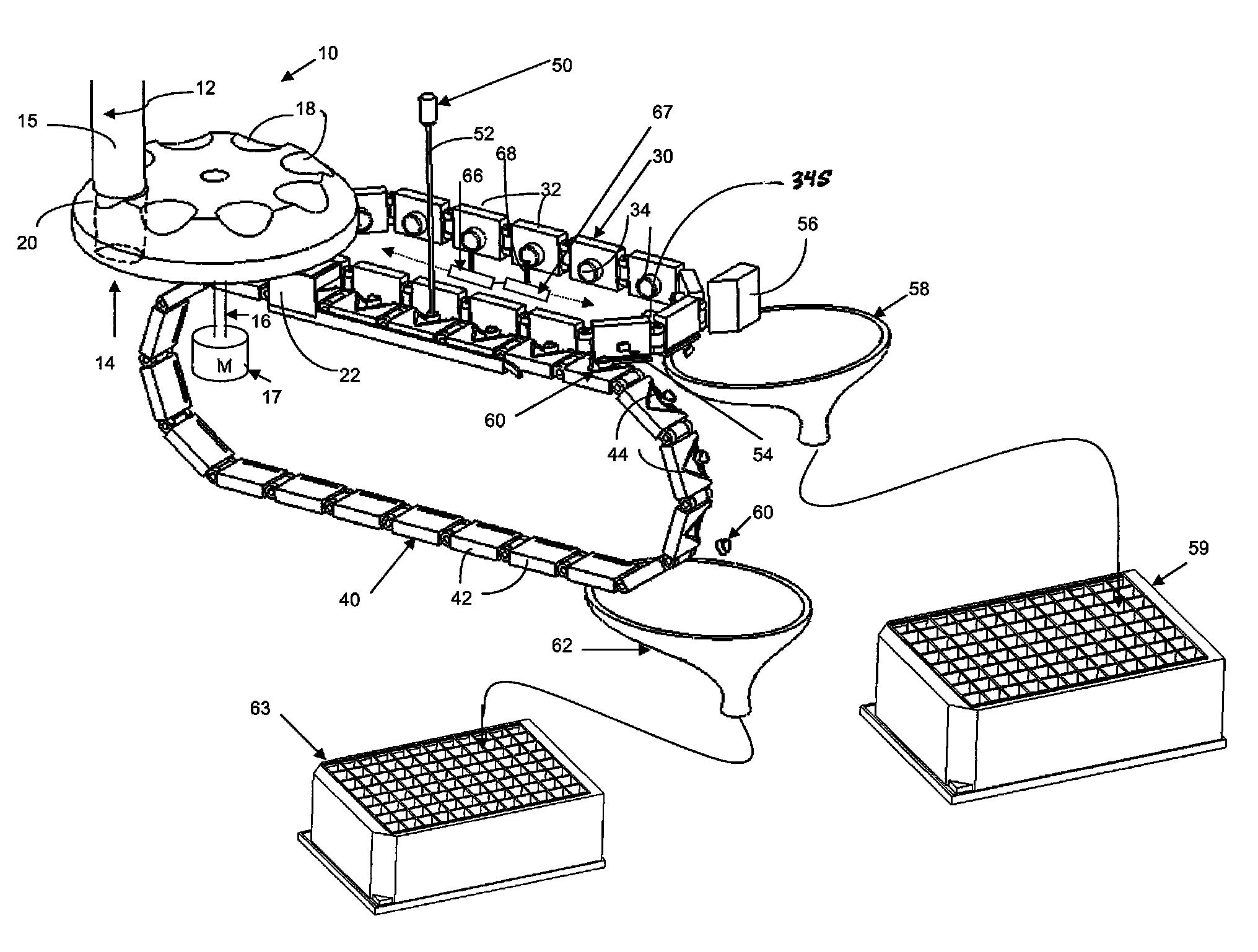
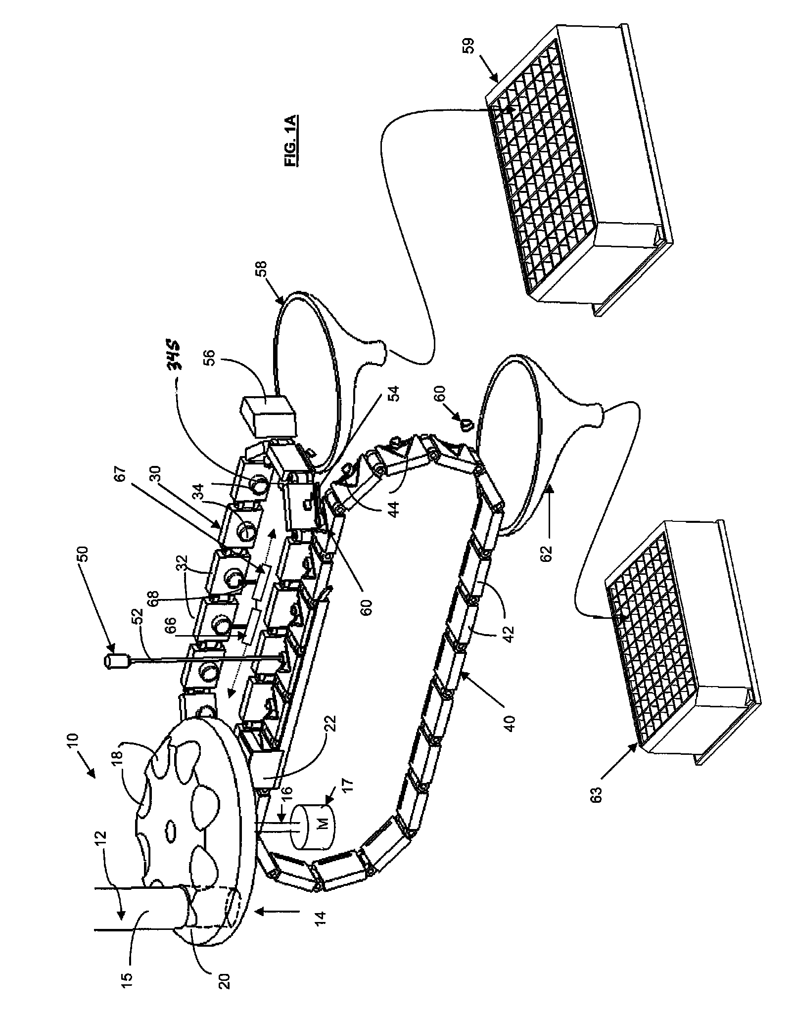
[0028]By referring to FIGS. 1A and B, a method, apparatus, and system according to one exemplary embodiment of the invention is shown. The goal is to position and orient a number of kernels of corn in a predetermined way so that a sample of each kernel from a consistent location on each kernel can be obtained.

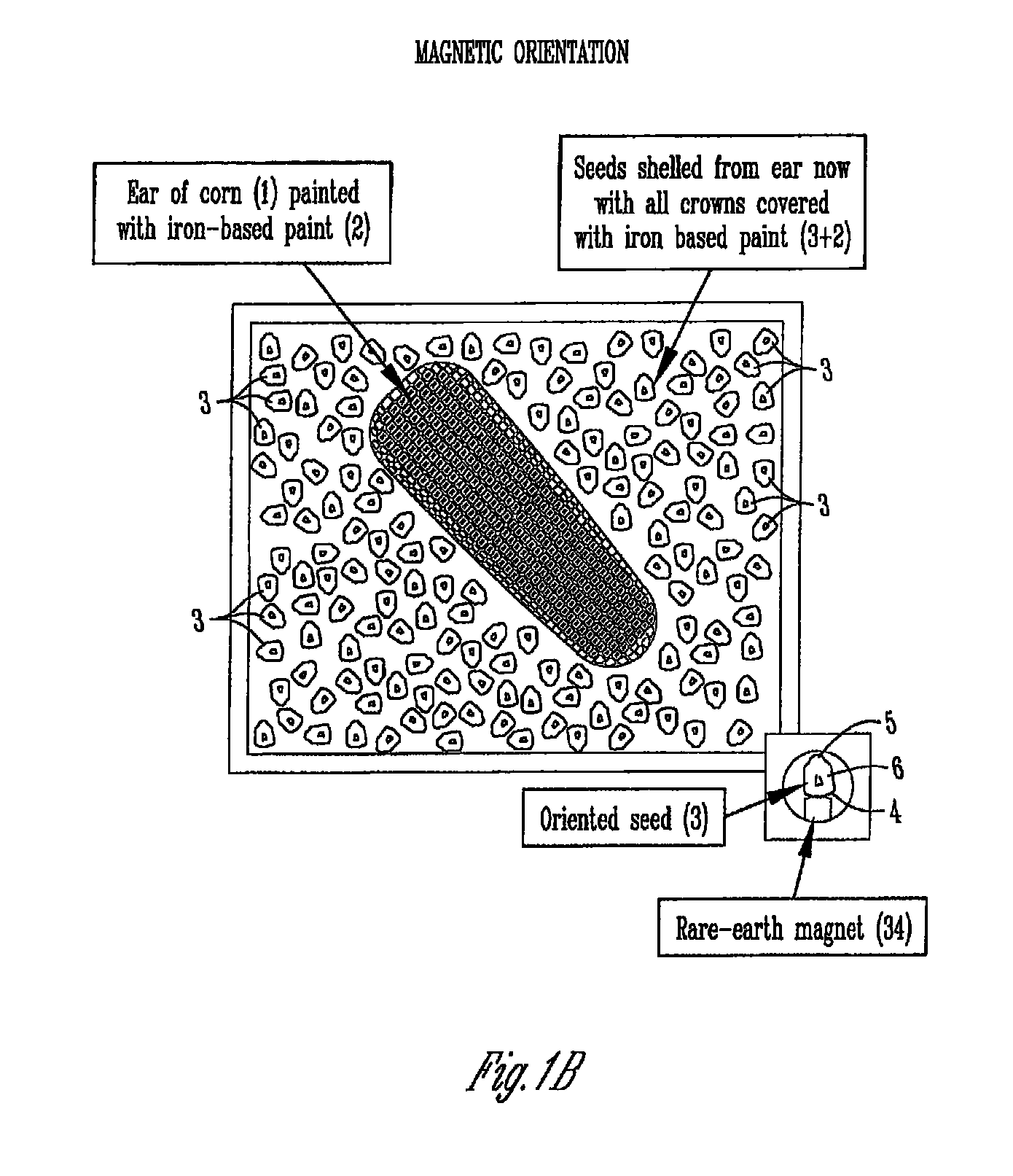
[0029]In this case the objects to be positioned and oriented are corn kernels. A substance is applied to each kernel prior to automatic orientation. In this example, the substance is a magnetically active paint.

[0030]The iron-based paint covering the crown of each seed and magnets 34 are utilized to automatically position and orient each singulated seed relative to a laser beam. An example of such iron-based paint is available commercially, namely Krylon® Magnetic Spray Paint (product # 3151, 13 oz. aerosol spray can from The Sherwin-Williams Co., Krylon Products Group, Cleveland, Ohio USA). It can be sprayed onto the exterior of ear of corn 1.

[0031...

embodiment 2

B. EMBODIMENT 2

FIG. 1C

[0056]As can be appreciated, the basic idea of magnetic positioning, orientation and, laser cutting can be accomplished in a variety of different ways with a variety of different components and methodologies. FIG. 1C shows an alternative embodiment to that of FIG. 1A. A similar buffer wheel 14 with individual receivers 18 rotated by a motor 17 with shaft 16 is shown. Additionally, a stationary disc 21, having a single opening above chute 22, holds seed in each well 18 of rotating buffer wheel 14 except for the well directly over the opening in disc 21 in alignment with chute 22. In this manner, individual seed 3 is dropped, one at a time and at spaced apart intervals.

[0057]The alternative embodiment of FIG. 1C mounts magnets 34 in through-holes in the rim of wheel 72 (e.g. by interference fit) such that a surface of each magnet 34 is directly exposed to the seed. Empirical testing can determine the precise desired magnet for a given embodiment.

[0058]In FIG. 1C,...

embodiment 3

D. EMBODIMENT 3

FIGS. 2A-C

[0069]Magnetic orientation is also used in system 100 of FIG. 2A. Magnet assembly 102 includes a base plate and forty-eight posts 104 extending downwardly from the base plate. A magnet 106 is positioned at or near the distal end of each post 104.

[0070]Posts 104 of magnet assembly 102 are inserted into complementary through-holes 112 in cutting assembly 110. The cutting assembly box or housing slideably retains cutting blade 114 in slot 116. Cutting blade has forty-eight openings 115 corresponding in position and spacing to the forty-eight through-holes 112, but the perimeter of each opening 115 is formed, sharpened, or otherwise configured to include a relatively sharp edge.

[0071]The combination of the magnet assembly 102 and the cutting assembly 110 is simultaneously lowered into seed box 108 (see FIG. 2C) filled with a mass of singulated seed 3, each with its crown painted with iron-based paint, as previously described (or otherwise a substance or componen...


PUM


Abstract

A method and apparatus for automatic positioning and / or orientation of an object. The method includes applying a substance or component to an object, or takes advantage of a substance or component already on or associated with an object. The substance or component has a characteristic that can be utilized to automatically attract the substance or component. That characteristic is used to position, move, and / or orient the object automatically, without requiring manual handling. The object can then be further processed or handled. In one embodiment, the substance or component is a magnetically active substance or component. The attraction can be actuated by a magnet.

Description

RELATION TO OTHER APPLICATIONS[0001]This invention claims priority under 35 U.S.C. Section 119 to U.S. Provisional Applications No. 60 / 865,563 and No. 60 / 865,554, both filed Nov. 13, 2006, each of which is incorporated by reference in its entirety.BACKGROUND OF THE INVENTION[0002]The present invention relates to automated handling of objects, and particularly, automatic positioning and / or orienting them.RELATED ART[0003]A variety of situations exist where relatively small, discrete objects or parts need to be handled, positioned, and sometimes placed in a specific orientation.[0004]A vast number of apparatus and methods have been developed over the years for sorting discrete objects, pieces, or components. For example, some sort on the basis of shape. Some sort on the basis of size. Some more complex systems even use such things as artificial or machine vision and sort on the basis of color or physical characteristics from image analysis.[0005]Sorting or discriminating between objec...

Claims


Application Information

Patent Timeline
Patent Type & Authority Patents(United States)
IPC IPC(8): B65G47/24
CPCG01N1/28G01N35/00G01N1/04B65G17/46B65G37/005B65G2201/0202B65G2203/044G01N2033/0077G01N35/0098
Inventor COPE, JASONKURTH, DAVID
Owner PIONEER HI BRED INT INC
Why Eureka
Try Eureka