
Leak detection using structure-borne noise

Inactive Publication Date: 2010-06-22
IOWA STATE UNIV RES FOUND
View PDF6 Cites 16 Cited by
  • Summary
  • Abstract
  • Description
  • Claims
  • Application Information

AI Technical Summary

Benefits of technology

[0017]Therefore, it is a primary object, feature, or advantage of the present invention to improve over the state of the art.
[0018]It is a further object, feature, or advantage of the present invention to provide for rapid detection of air leaks in a spacecraft skin, such as those caused by impact with space debris or meteorites.
[0019]Another object, feature, or advantage of the present invention is the detection of air leaks in a spacecraft skin by using ultrasonic waves in the spacecraft skin and not just airborne noise.
[0020]Yet another object, feature, or advantage of the present invention is to provide a continuous system for leak detection and the determination of leak location.
[0021]A further object, feature, or advantage of the present invention is to provide for a method and system for detection of air leaks that is capable of accommodating multiple dispersive modes of plate wave propagation.
[0022]A further object, feature, or advantage of the present invention is to provide a framework for leak detection of a pressure vessel flexible enough to allow a number of different of sensor configurations and corresponding specific methodologies to be used.

Problems solved by technology

It has been well known for a long time that orbital objects, such as meteoroids and space debris, are among the serious, but inevitable, threats to spacecraft intended for prolonged habitation.
The strikes of small objects between 0.10 and 10.0 mm cannot, however, be avoided using the current devices.
Furthermore, because the objects strike the spacecraft at high speeds, up to 10 to 15 km / s [3], even small particles in the size range of 1 mm could result in penetration of the pressure vessel and subsequent loss of air.
Clearly, there will a higher probability of collisions with smaller objects if space exploration includes trips with longer operational times.
In particular, the impacts of small objects cause air leaks when they strike a pressurized module on the ISS.
As reported by NASA in January 2004 [9], parts of the ISS were nearly closed off for three weeks due to the air leaks.
Although the size of the air leak was too small to endanger the crew and mission immediately, it was a time-consuming process to find and seal the leaks.
However, regardless of size of the air leaks, the detection and location of air leaks is a very difficult and time-consuming process because the size of an ISS module and the complexity of its construction.
The crew cannot inspect the entire series of modules immediately.
In addition, the ultrasound noise generated by escaping air at supersonic speed from small holes into the vacuum of space is not audible or detectable inside the ISS because of the nature of the leaks.
The process involves very inefficient and time-consuming tasks, where the crew monitors the pressure difference while sequentially closing each hatch.
Because it is not easy to discern very small pressure differences, the isolation process still does not reduce the leak detection time and risk of the crew's safety.
So, the crew must stop all the venting systems in a suspicious module to find air-leaks, and this action could cause more serious problems.
In addition, pinpointing a leak location is not possible because the sensors are designed only to localize leaking to a specific module losing a measurable amount of air, and not to find its exact location within the module.
In the lab test, the sensor can detect the airborne noise in air escaping from a surgical needle at a distance of approximately 5 m. However, due to the nature of its working principle, it is not an efficient detector or locator of leaks inside a module.
Instead, the crew must use the sensor outside of the module, an extremely time-consuming and often dangerous activity.
However, the detectable zone is very small and restricted so that it is not a fully functional sensor to locate air leaks on a large-scale space station.
This method, however, is based on the same principle as most of the other industrial leak detectors, and is also not efficient for locating air leaks on the ISS because it was originally designed to detect leaks from pressurized vessels, where air is escaping into an atmospheric environment of 1 bar from a pressurized vessel at a pressure of at least 1 bar gage, or 2 bar absolute.
Although this detector is not designed to find the exact location of air leaks on the ISS, it provides the crew with valuable information when they are tracking down suspicious leak locations.
When air leaks occur, the vent thrust generates a small torque on the space station.
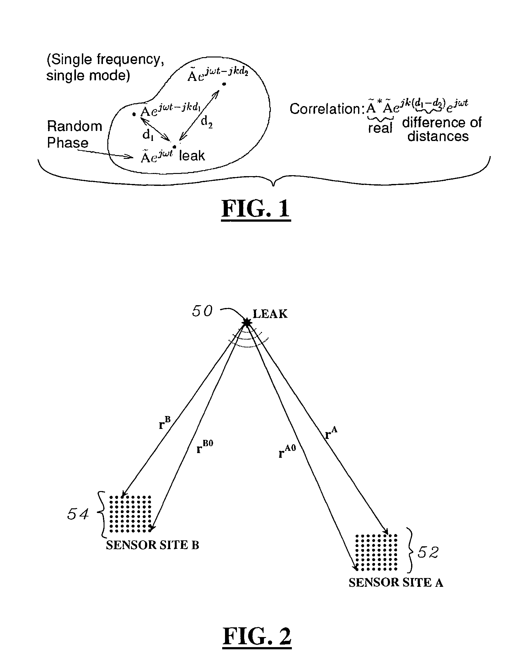
The time delay corresponds to the distance between the sensors and the leak source.
However, the results of the cross correlation do not clearly show a large peak.
Although a simple cross correlation method is marginally capable of locating the leaks, it provides unambiguous indications of a leak only if it satisfies the simplified assumption of a single mode of propagation with a non-dispersive (or frequency-independent) wave speed.
In a dispersive medium, the structure-borne noise propagates with a different velocity at every frequency so that the cross correlation technique is not suitable to adequately provide an exact location of the leak source.
The method provides much poorer results as the received signals become more dispersive.
Furthermore, the effect of the dispersion becomes more serious as the distance between the sensors at remote locations and the leak source increases.
As a result, the cross correlation technique is not a viable option to locate leaks in dispersive media or structures.
Despite these works, significant problems remain in leak detection.

Method used


Image

  • Leak detection using structure-borne noise
  • Leak detection using structure-borne noise
  • Leak detection using structure-borne noise

Examples


Embodiment Construction

[0045]The present provides for detection of leaks and location of the leaks in pressure vessels, such, as but not limited to a spacecraft. Although spacecraft are referred to throughout the specification, it is to be understood that spacecraft are being used merely as one example of a pressure vessel for which detection and location determination of leaks is desired. The present invention is not to be limited to this specific use.

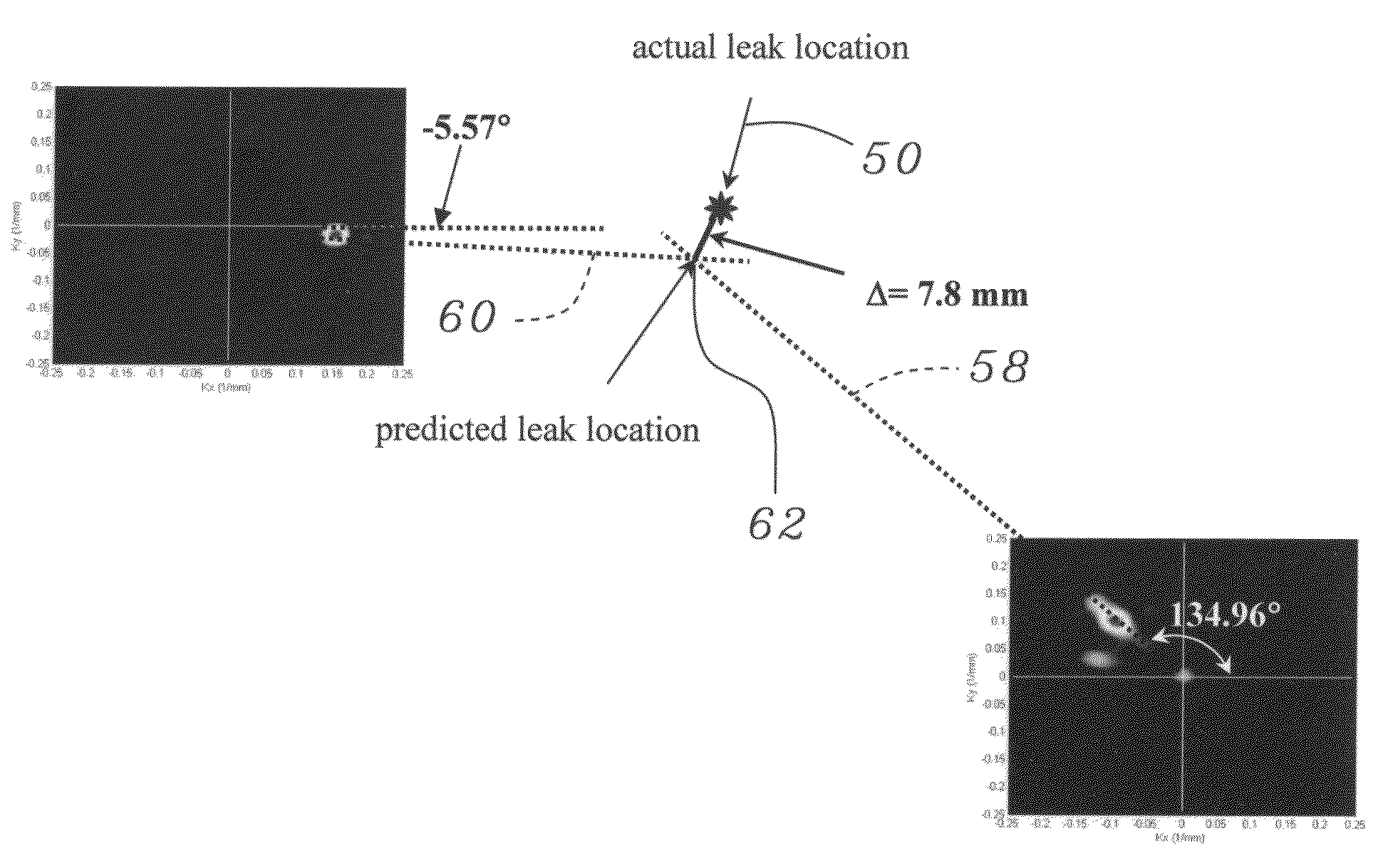
[0046]The present invention recognizes that, in the case of a space craft, listening inside the cabin to locate a leak is ineffective. The present invention provides for listening to structure borne ultrasonic noise in the skin of the spacecraft. If a leak is present, turbulence in the leaking air will generate noise in the plate and in the air. Leak noise which couples to the plate-like skin of the spacecraft is carried away from the leak site as guided ultrasonic Lamb waves. By monitoring and analyzing these waves propagating within the skin of the spacec...


PUM


Abstract

A method for detection and location of air leaks in a pressure vessel, such as a spacecraft, includes sensing structure-borne ultrasound waveforms associated with turbulence caused by a leak from a plurality of sensors and cross correlating the waveforms to determine existence and location of the leak. Different configurations of sensors and corresponding methods can be used. An apparatus for performing the methods is also provided.

Description

RELATED APPLICATIONS[0001]This application claims priority to U.S. Provisional Patent Application No. 60 / 676,428, filed Apr. 29, 2005, hereby incorporated by reference in its entirety.GRANT REFERENCE[0002]The work presented in this application was supported in part by a federal grant from the NASA, Grant No. NAG-1-02098, the government may have certain rights in this invention.BACKGROUND OF THE INVENTION[0003]The present invention relates to leak detection and determining leak location. To assist in understanding the present invention, problems related to detecting and locating air leaks in spacecraft are described. It should be understood, however, that the present invention can be used for detection of leaks and location of leaks in any number of other types of vessels, particularly pressure vessels, and is in no way limited to spacecraft.[0004]It has been well known for a long time that orbital objects, such as meteoroids and space debris, are among the serious, but inevitable, t...

Claims


Application Information

Patent Timeline
IPC IPC(8): G01M3/04
CPCG01M3/24
Inventor HOLLAND, STEPHEN D.CHIMENTI, DALE E.ROBERTS, RONALD A.
Owner IOWA STATE UNIV RES FOUND
Learn More