
Acoustic crosstalk reduction for capacitive micromachined ultrasonic transducers in immersion

a micro-machined ultrasonic and capacitive technology, applied in the direction of generator/motor, mechanical vibration separation, instruments, etc., can solve the problems of reducing the dispersion guided mode of an ultrasonic signal, and the performance of the transducer in immersion is degraded, so as to reduce crosstalk and reduce capacitance

Active Publication Date: 2010-06-29
THE BOARD OF TRUSTEES OF THE LELAND STANFORD JUNIOR UNIV
View PDF7 Cites 27 Cited by
  • Summary
  • Abstract
  • Description
  • Claims
  • Application Information

AI Technical Summary

Benefits of technology

"The present invention provides a reduced crosstalk capacitive micromachined ultrasonic transducer (CMUT) array with a membrane between adjacent CMUT elements to reduce crosstalk. The separation regions between the elements are substantially the same, creating a periodicity in the CMUT elements. The CMUT cells within the elements are also substantially the same, creating a periodicity in the CMUT cells. The CMUT operates in a conventional mode or a collapsed mode to transmit and receive ultrasound. The CMUT cell has an insulation layer, a cell membrane layer with a gap, an electrode layer covering a portion of the membrane layer, and a passivation layer. The gap can be a vacuum gap or the CMUT cell can have a geometry such as circular, square, hexagonal, or tented. The insulation layer, membrane layer, electrode layer, and passivation layer can be made from silicon nitride or silicon oxide, and the membrane layer and electrode layer can be made from aluminum or gold. The passivation layer can be made from silicon nitride or silicon oxide."

Problems solved by technology

This coupling degrades the performance of transducers in immersion for medical applications such as diagnostic imaging and high intensity focused ultrasound (HIFU) treatment.
However the problem of reducing the dispersive guided mode of an ultrasonic signal remained unaddressed.

Method used


Image

  • Acoustic crosstalk reduction for capacitive micromachined ultrasonic transducers in immersion
  • Acoustic crosstalk reduction for capacitive micromachined ultrasonic transducers in immersion
  • Acoustic crosstalk reduction for capacitive micromachined ultrasonic transducers in immersion

Examples


Embodiment Construction

[0035]Although the following detailed description contains many specifics for the purposes of illustration, anyone of ordinary skill in the art will readily appreciate that many variations and alterations to the following exemplary details are within the scope of the invention. Accordingly, the following preferred embodiment of the invention is set forth without any loss of generality to, and without imposing limitations upon, the claimed invention.

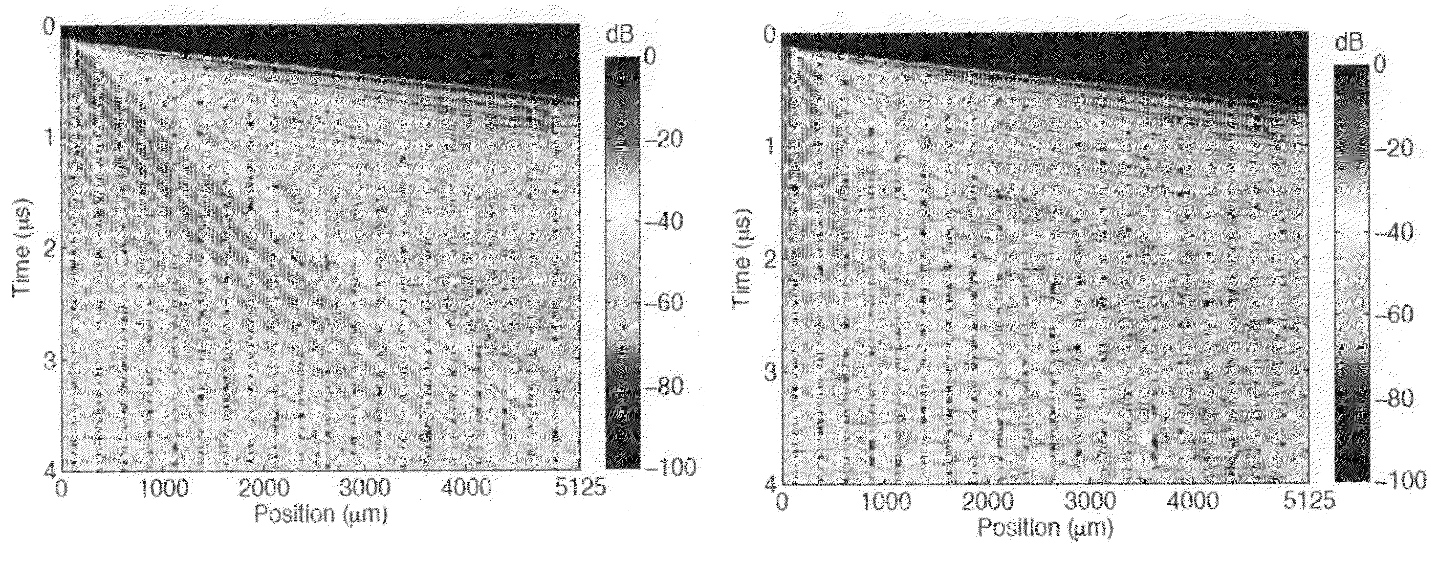
[0036]The premise of crosstalk reduction stems from several observations and how they relate to the current invention to reduce the crosstalk, the observations are as follows:[0037]1) The main crosstalk mechanism is the dispersive guided mode (−23 dB) propagating in the fluid-solid interface compared to A0 (−40 dB) and S0 (−65 dB) Lamb Wave modes. The current invention reduces the crosstalk and impedes the propagation of this guided mode.[0038]2) This guided mode disappears close to 4 MHz, corresponding to the membrane resonance in immers...


PUM


Abstract

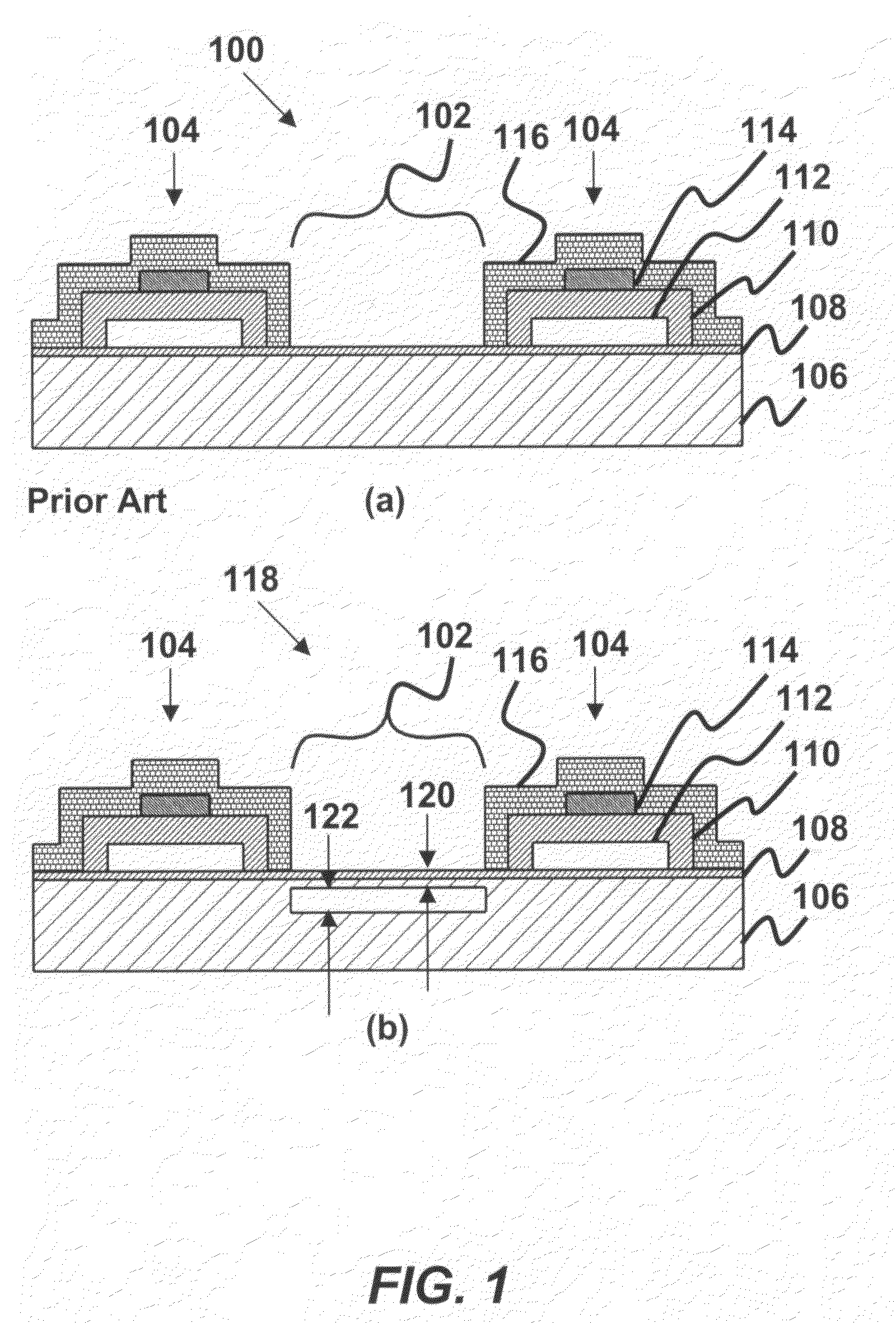
A reduced crosstalk capacitive micromachined ultrasonic transducer (CMUT) array is provided. The CMUT array has at least two CMUT array elements deposited on a substrate, at least one CMUT cell in the array element, a separation region between adjacent CMUT array elements, and a membrane formed in the separation region. The membrane reduces crosstalk between adjacent array elements, where the crosstalk is a dispersive guided mode of an ultrasonic signal from the CMUT propagating in a fluid-solid interface of the CMUT array. Each cell has an insulation layer deposited to the substrate. A cell membrane layer is deposited to the insulation layer, where the cell membrane layer has a vacuum gap therein. The cells further have an electrode layer deposited to a portion of the membrane layer, and a passivation layer deposited to the electrode layer, the cell membrane layer and to the insulation layer.

Description

CROSS-REFERENCE TO RELATED APPLICATIONS[0001]This application is cross-referenced to and claims the benefit from U.S. Provisional Patent Application 60 / 797,489 filed May 3, 2006 which is hereby incorporated by reference.STATEMENT REGARDING FEDERALLY SPONSORED RESEARCH OR DEVELOPMENT[0002]The present invention was supported in part by grant number HL67647 from the National Institute of Health, and supported in part by grant number N00014-02-1-0007 from the United States Office of Naval Research. The U.S. Government has certain rights in the invention.FIELD OF THE INVENTION[0003]The invention relates generally to capacitive micromachined ultrasonic transducers (CMUTs). More particularly, the invention relates to apparatus and methods for reducing acoustic crosstalk between the elements of CMUT arrays in immersion by placing a membrane in the separation region between neighboring array elements.BACKGROUND[0004]Microfabrication technology that employed the techniques originally develope...

Claims


Application Information

Patent Timeline
Patent Type & Authority Patents(United States)
IPC IPC(8): H01L41/08H10N30/00
CPCB06B1/0292
Inventor BAYRAM, BARISKHURI-YAKUB, BUTRUS T.
Owner THE BOARD OF TRUSTEES OF THE LELAND STANFORD JUNIOR UNIV
Learn More