Cardiac valve procedure methods and devices

a cardiac valve and valve technology, applied in the field of surgical procedures and devices, can solve the problems of one effective treatment for patients with aortic arteries, substantial and invasive undertaking for patients, and little progress in the development of safer and less invasive valve delivery systems, so as to enable the performance of an operation

Active Publication Date: 2010-07-06
MEDTRONIC INC
View PDF40 Cites 38 Cited by
  • Summary
  • Abstract
  • Description
  • Claims
  • Application Information

AI Technical Summary

Benefits of technology

[0019]The temporary filter acts to prevent emboli that may be dislodged during the valve procedure from moving distal to the filter. In a preferred method of use, the filter is placed in the aorta proximal to the braciolcephalic artery to prevent emboli from reaching the brain. The filter can be one of a variety of designs, including, but not limited to a mesh filter with a pore size smaller than the dimensions of anticipated embolic particles. The filter can be inserted directly into the aorta or advanced into the aorta from a peripheral artery. It is preferably inserted in a compressed state and expands or is expanded to a larger state at a desired site within the aorta.
[0022]Another aspect of the present invention is a method of performing a procedure on a beating heart involving, at a minimum, inserting into the aorta, a temporary valve, as described above, removing at least some portion of the native aortic valve, and placing a permanent valve prosthesis at a site within the aorta. The temporary valve allows removal of the native valve while reducing the risk of heart failure due to insufficiency of the native valve. Removal of at least some portion of the native valve can be carried out with one or a variety of tools that can be inserted either directly into the aorta or through a peripheral artery and advanced to the native valve. Similarly, the permanent valve prosthesis can be inserted either directly into the aorta or advanced into the aorta from a peripheral artery. The valve prosthesis is preferably inserted in a compressed state and expands or is expanded at the desired implantation site. The implantation site is preferably proximal to the coronary arteries, but can be at any suitable location in the aorta. The valve can be one of a variety of types known in the art, but is preferably a flexible valve suitable for inserting into an artery in a compressed state. This method can further involve the placement of a temporary filter as described above to reduce the risk of emboli generated during manipulation of the native valve. As described above, the temporary filter can be a separate device or an integral component of the temporary valve.

Problems solved by technology

Currently, there is only one effective treatment for patients with aortic stenosis-aortic valve replacement via open heart surgery.
Unfortunately, this is a substantial and invasive undertaking for the patient.
While there have been significant advances in heart valve technology over the last thirty years, there has been little progress in the development of safer and less invasive valve delivery systems.
This procedure is accompanied by a 5% mortality rate, in addition to significant morbidity (stroke, bleeding, myocardial infarction, respiratory insufficiency, wound infection) related to the use of cardiopulmonary bypass and the approach to the aortic valve.
Elderly patients and those who require concomitant coronary artery bypass grafting experience increased morbidity and mortality.
Using the technology available at that time, success was limited.
These approaches still require cardiopulmonary bypass and cardiac arrest, which entail significant morbidity and a prolonged postoperative recovery.
Although there has been great progress in the treatment of coronary artery disease without cardiopulmonary bypass (angioplasty / stenting and “off-pump” coronary artery bypass grafting), similar advances have not yet been realized in heart valve surgery.
There are three significant challenges to replacing a diseased aortic valve without cardiopulmonary bypass.
When the valve becomes acutely and severely incompetent during removal, the patient develops heart failure leading to death unless the function of the valve is taken over by another means.
First, they tend to occupy a significant length of the vessel when deployed.
The valves disclosed to date tend also to be rather flimsy and may have difficulty supporting the fluid pressures while the valve is closed.
A more significant disadvantage of these valves is that they generally must be inserted into a vessel at a significant distance from the valve to allow adequate room for deployment.
This adds morbidity and complexity to the procedure.
Another drawback of the prior art is that valves with three or fewer leaflets rely on the perfect performance of each of those leaflets.
If one of the leaflets malfunctions, the valve fails to function adequately.

Method used


Image

  • Cardiac valve procedure methods and devices
  • Cardiac valve procedure methods and devices
  • Cardiac valve procedure methods and devices

Examples


embodiment

Preferred Embodiment

Valved Arch Filter

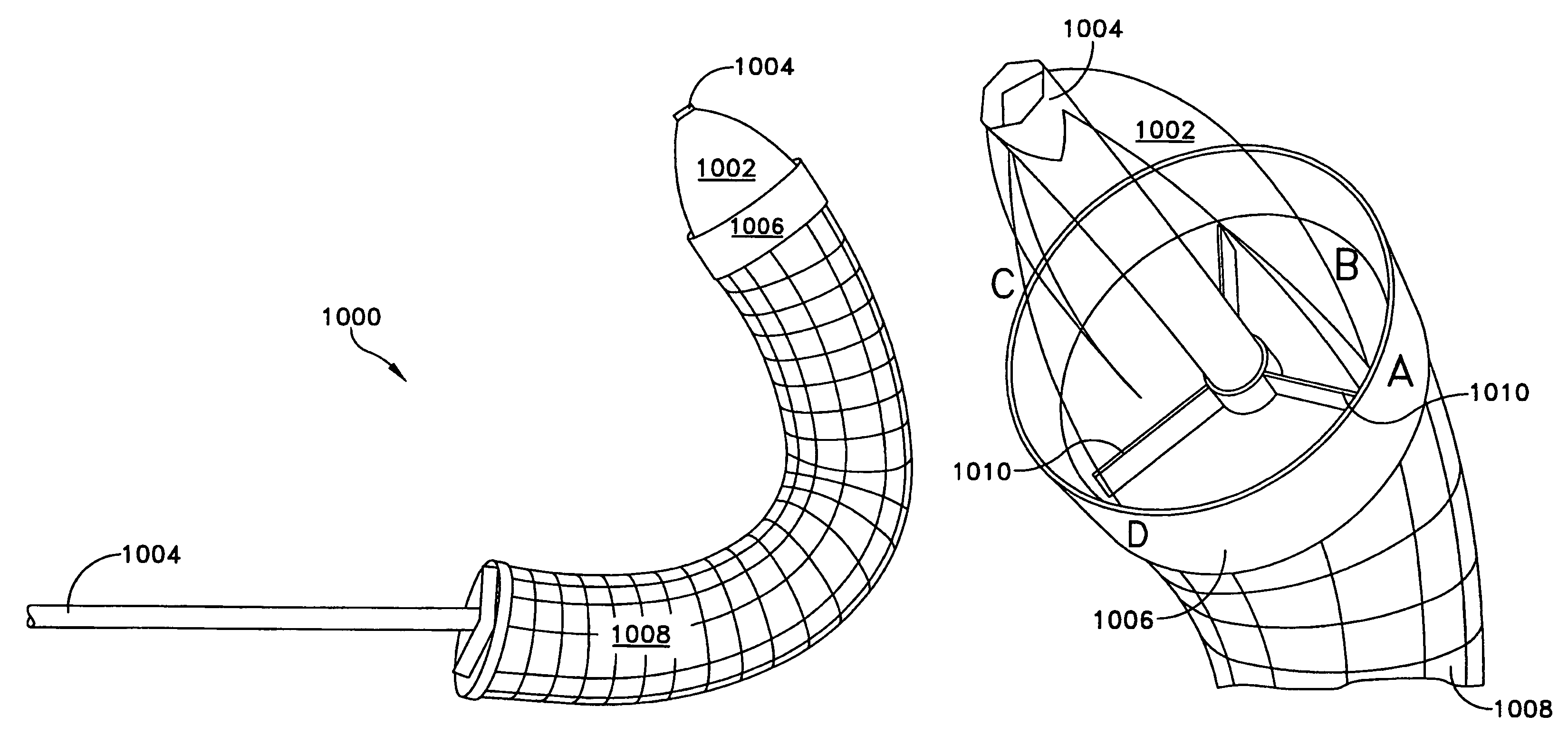
[0154]In accordance with a further feature of the invention, there is provided a novel valved arch filter device 1000 (FIG. 25) which provides a temporary one-way valve between the coronary ostia (where the coronaries come off the aorta) and the origin of the great vessels (i.e., those going to the arms and brain).

[0155]The temporary one-way valve performs the function of the native aortic valve during the brief period after the native diseased valve has been removed and before a prosthetic valve has been implanted. Ideally, this temporary valve would sit in exactly the same position as the natural valve, but this area needs to be kept free for fixation of the prosthesis. Therefore, the temporary valve is located downstream from the natural aortic valve. In this position, the left ventricle is spared the hemodynamic stress of acute severe aortic insufficiency. That is to say, if one simply removed the aortic valve on a beating, unassisted heart ...


PUM


Abstract

Devices and methods for performing intravascular procedures without cardiac bypass include embodiments of temporary filter devices, temporary valves, and prosthetic valves. The temporary filter devices have a cannula which provides access for surgical tools for effecting repair of cardiac valves. The cannula may have filters which prevent embolitic material from entering the coronary arteries and aorta. The valve devices may also have a cannula for insertion of the valve into the aorta. The valve devices expand in the aorta to occupy the entire flow path of the vessel and operate to prevent blood flow and to permit flow through the valve. The prosthetic valves include valve fixation devices which secure the prosthetic valve to the wall of the vessel. The prosthetic valves are introduced into the vascular system in a compressed state, advanced to the site of implantation, and expanded and secured to the vessel wall.

Description

REFERENCE TO PENDING PRIOR APPLICATIONS[0001]This patent application is a continuation-in-part of U.S. application Ser. No. 09 / 700,167, filed Nov. 9, 2000, now U.S. Pat. No. 6,896,690, which is a section 371 National Stage of PCT / US00 / 02126, filed Jan. 27, 2000.[0002]This patent application is a continuation-in-part of U.S. application Ser. No. 09 / 896,258, filed Jun. 29, 2001, now U.S. Pat. No. 6,692,513 and is a continuation-in-part of U.S. application Ser. No. 10 / 022,951, filed Dec. 14, 2001, now U.S. Pat. No. 6,929,653, and is a continuation in part of U.S. application Ser. No. 09 / 896,259, filed Jun. 29, 2001, now U.S. Pat. No. 6,769,434, and is a continuation-in-part of U.S. application Ser. No. 10 / 014,699, filed Oct. 26, 2001, now U.S. Pat. No. 6,890,330.[0003]This patent application also claims benefit of:[0004]U.S. Provisional Patent application Ser. No. 60 / 425,877, filed Nov. 13, 2002 by William E. Cohn for CARDIAC VALVE PROCEDURE METHODS AND DEVICES.[0005]All of the above-i...

Claims


Application Information

Patent Timeline
Patent Type & Authority Patents(United States)
IPC IPC(8): A61M29/00A61F2/06A61F2/24
CPCA61F2/2412A61F2/2427A61F2250/0059A61F2220/0016
Inventor COHN, WILLIAM E.LAMBRECHT, GREGORY H.LIDDICOAT, JOHN R.MOORE, ROBERT KEVINSTREETER, RICHARD B.DAVENPORT, TODD F.
Owner MEDTRONIC INC
Why Eureka
Try Eureka