
Hydrocarbon adsorption method and device for controlling evaporative emissions from the fuel storage system of motor vehicles

a technology of hydrocarbon adsorption and fuel storage system, which is applied in the direction of combustion-air/fuel-air treatment, separation processes, applications, etc., can solve the problems of reducing adsorption capacity, reducing the amount of fuel vapor released into the atmosphere, and a significant environmental impa

Active Publication Date: 2010-07-13
BASF CATALYSTS LLC
View PDF57 Cites 31 Cited by
  • Summary
  • Abstract
  • Description
  • Claims
  • Application Information

AI Technical Summary

Benefits of technology

"The evaporative emission control apparatus is designed to reduce fuel vapor released into the atmosphere from a vehicle's engine. It includes a fuel storage system, a canister containing a hydrocarbon adsorbent, and a clean air vent line. The canister removes fuel vapor from the air using the adsorbent, and the purge stream of atmospheric air introduced during engine operation desorbs the hydrocarbons and recirculates them to the engine for combustion. The canister also contains a support substrate coated with a hydrocarbon adsorbent slurry for further reduction of evaporative hydrocarbon emissions. The patent text describes a technical solution for controlling evaporative emissions in vehicles and improving air quality."

Problems solved by technology

Due to the large number of automobile refuelings, such releases of fuel vapor constitute a significant hazard to the environment, particularly in heavily populated areas.
If this flow of air is left untreated and is allowed to escape directly into the atmosphere, undesirable emissions occur.
Due to incomplete desorption of the hydrocarbons, minute levels of hydrocarbons may remain stored in the adsorbent material of a purged evaporative canister.
If conditions favor desorption (e.g., incomplete desorption of the adsorbent, thereby lowering adsorption capacity), the air may carry bleed emissions out of the canister and into the atmosphere.
However, as worldwide evaporative emission regulations become more and more stringent, the technical limitations of carbon-based systems become more and more apparent.
In particular, an excessively high “bleed” rate or the formation of a permanent hydrocarbon heel often make the design and use of carbon-based systems problematic.
Although zeolites are generally more expensive than carbon, the hydrocarbon adsorption properties of zeolites may overcome the inherent bleed rate and heel formation problems associated with carbon.
), inorganic type binders are often not suitable since their binding characteristics are severely diminished.
However, without proper choice of these stabilizing agents, interparticle agglomeration of zeolite particles or coagulation of zeolite and binder particles will occur, thus rendering the slurry unstable for coating application.

Method used


Image

  • Hydrocarbon adsorption method and device for controlling evaporative emissions from the fuel storage system of motor vehicles
  • Hydrocarbon adsorption method and device for controlling evaporative emissions from the fuel storage system of motor vehicles
  • Hydrocarbon adsorption method and device for controlling evaporative emissions from the fuel storage system of motor vehicles

Examples


Embodiment Construction

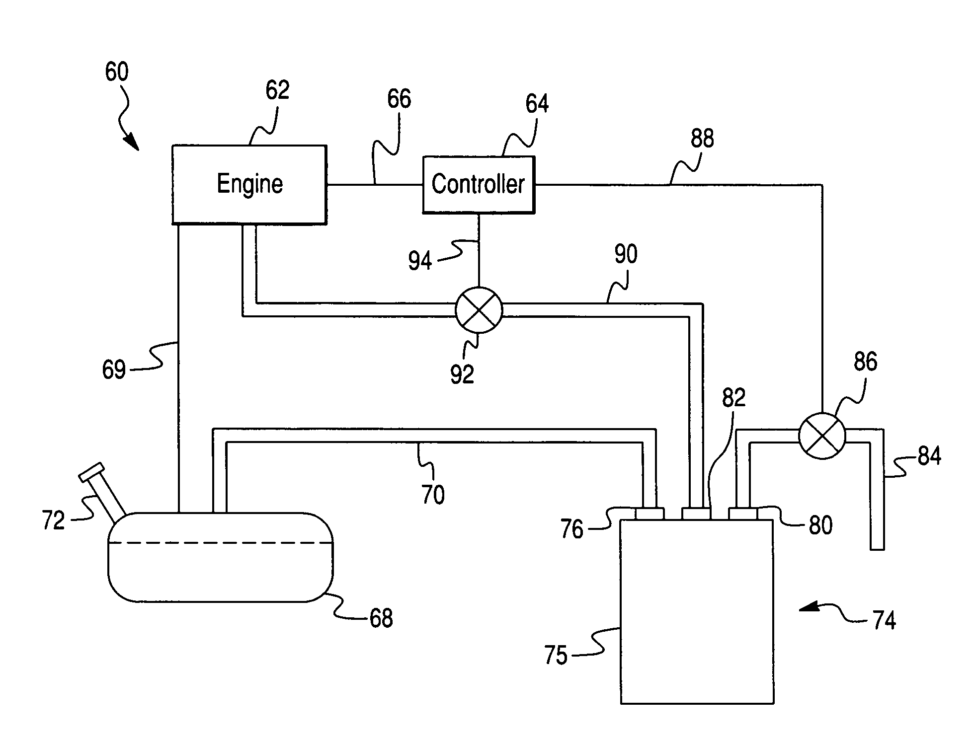
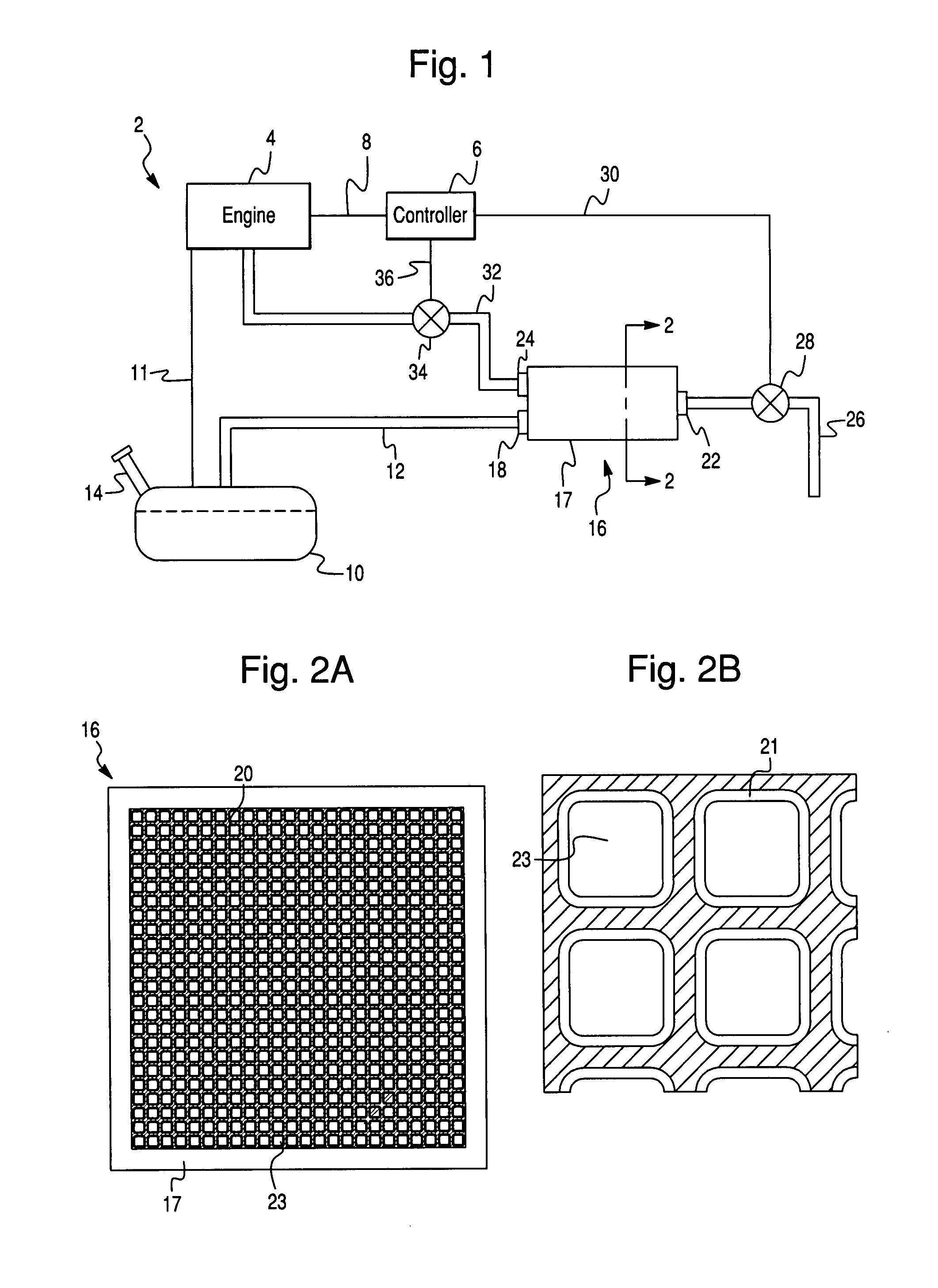
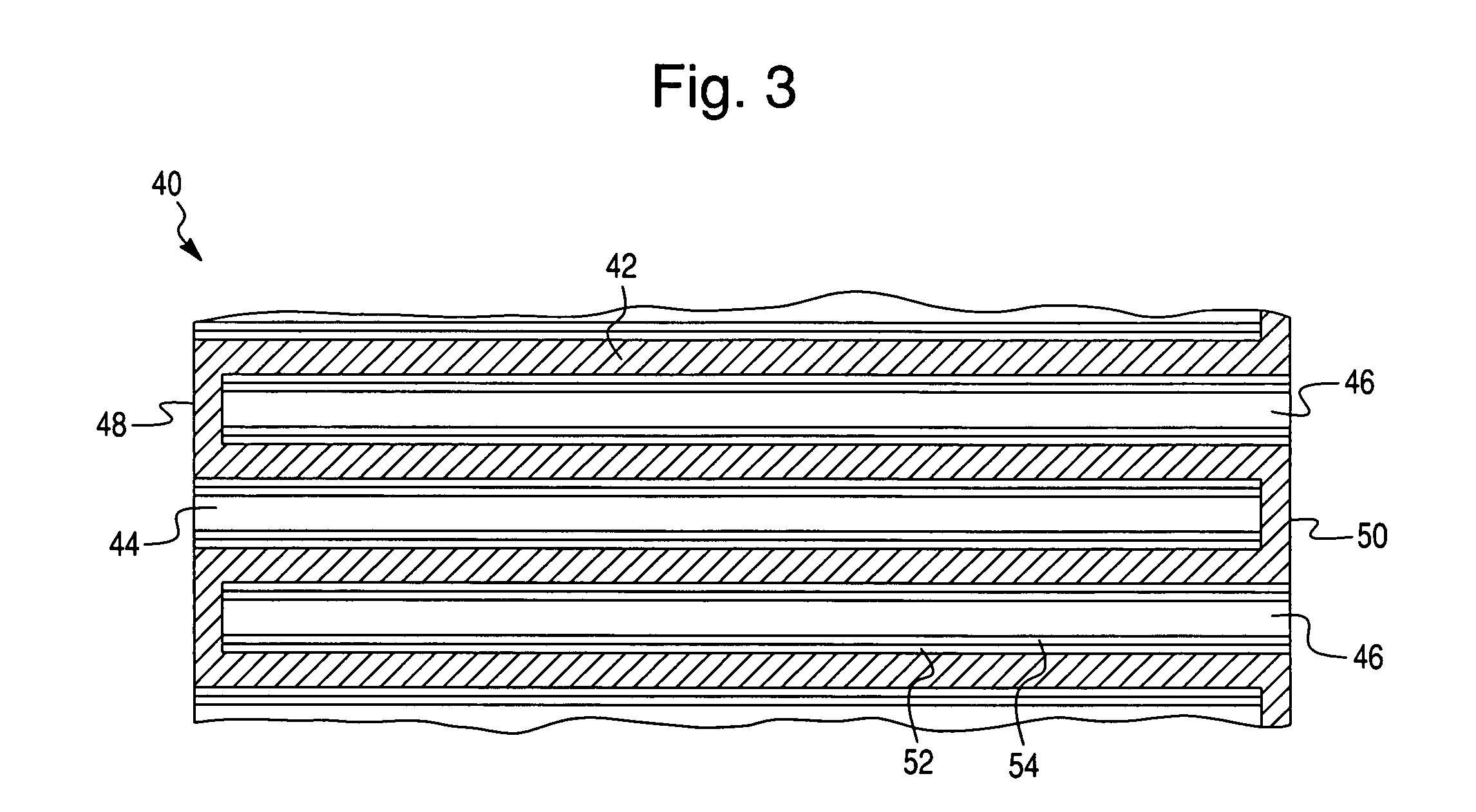
[0032]The evaporative emission control apparatus of the present invention comprises a fuel storage system, e.g., a fuel tank, an evaporative vapor vent line, a canister containing a hydrocarbon adsorbent, and a clean air vent line to the atmosphere. In one embodiment, the canister is filled with hydrocarbon adsorbent particles. In another embodiment, the hydrocarbon adsorbent material is formulated into a slurry that is coated onto a support substrate, e.g., a flow through monolithic support, that is placed within the evaporative emission treatment canister.

[0033]Referring now to FIGS. 1 and 2, an evaporative emission control system 2 for a vehicle including an engine 4 is illustrated and represents one non-limiting embodiment of the present invention. The evaporative emission control system 2 of this embodiment comprises a fuel tank 10, an evaporative vapor vent line 12, a canister 16 containing a hydrocarbon adsorbent material 21, and a clean air vent line 26 to the atmosphere. Th...


PUM

PropertyMeasurementUnit
temperaturesaaaaaaaaaa
pore sizeaaaaaaaaaa
diameteraaaaaaaaaa

Abstract

The present invention is directed to an evaporative emissions control apparatus for minimizing fuel vapor emissions from a fuel storage system in a vehicle with an internal combustion engine. More specifically, the present invention is directed to an evaporative emissions control apparatus comprising a canister filled with a hydrocarbon adsorbent. The present invention is also directed an evaporative emissions control apparatus comprising a support substrate, which is coated with a hydrocarbon adsorbent slurry.

Description

FIELD OF THE INVENTION[0001]This invention is directed to a method and device for controlling evaporative hydrocarbon emissions from motor vehicles. More specifically, this invention is directed to a method and device for adsorbing hydrocarbon vapors within the fuel storage system of the motor vehicle before the hydrocarbon vapors can be released to the atmosphere.BACKGROUND OF THE INVENTION[0002]When fuel is added to a fuel reservoir, such as the gasoline tank of an automobile from a conventional gas dispenser apparatus such as the dispensing nozzle of a gasoline dispenser, gasoline vapor is displaced from the gasoline tank. If the vapor is not collected in some way, it will be released into the atmosphere. Due to the large number of automobile refuelings, such releases of fuel vapor constitute a significant hazard to the environment, particularly in heavily populated areas. Releases of these vapors which are composed of volatile organic compounds (VOC's) such as hydrocarbons, are ...

Claims


Application Information

Patent Timeline
Patent Type & Authority Patents(United States)
IPC IPC(8): F02M33/02
CPCB01D53/02F02M25/089F02M25/0854B01D2253/108B01D2253/342B01D2259/4516B01D2257/702F02M25/08B60K15/035B01D53/04
Inventor HOKE, JEFFREY BARMONTBUELOW, MARK THOMASKAUFFMAN, JOHN JOSEPH
Owner BASF CATALYSTS LLC
Learn More