Catalytically activated transient decomposition propulsion system

a propulsion system and catalytic activation technology, applied in the field of propulsion systems, can solve the problems of reducing performance, reducing performance, and reducing performance, so as to improve performance and control, improve performance, and improve performan

Inactive Publication Date: 2010-07-20
THE AEROSPACE CORPORATION
View PDF10 Cites 6 Cited by
  • Summary
  • Abstract
  • Description
  • Claims
  • Application Information

AI Technical Summary

Benefits of technology

[0012]Yet another object of the invention is to provide a catalytic decomposition propulsion system using an opening and closing control valve for feeding a decomposing propellant into a decomposition chamber having a plurality of beds with respectively sized bedding for supporting respectively sized catalytic particles for improved thrusting performance.
[0014]A further object of the invention is to provide a catalytic decomposition propulsion system using an opening and closing control valve for feeding a decomposing propellant into a decomposition chamber attached to a recirculation tube for feeding back pressurized gas into an injector manifold for improved performance.
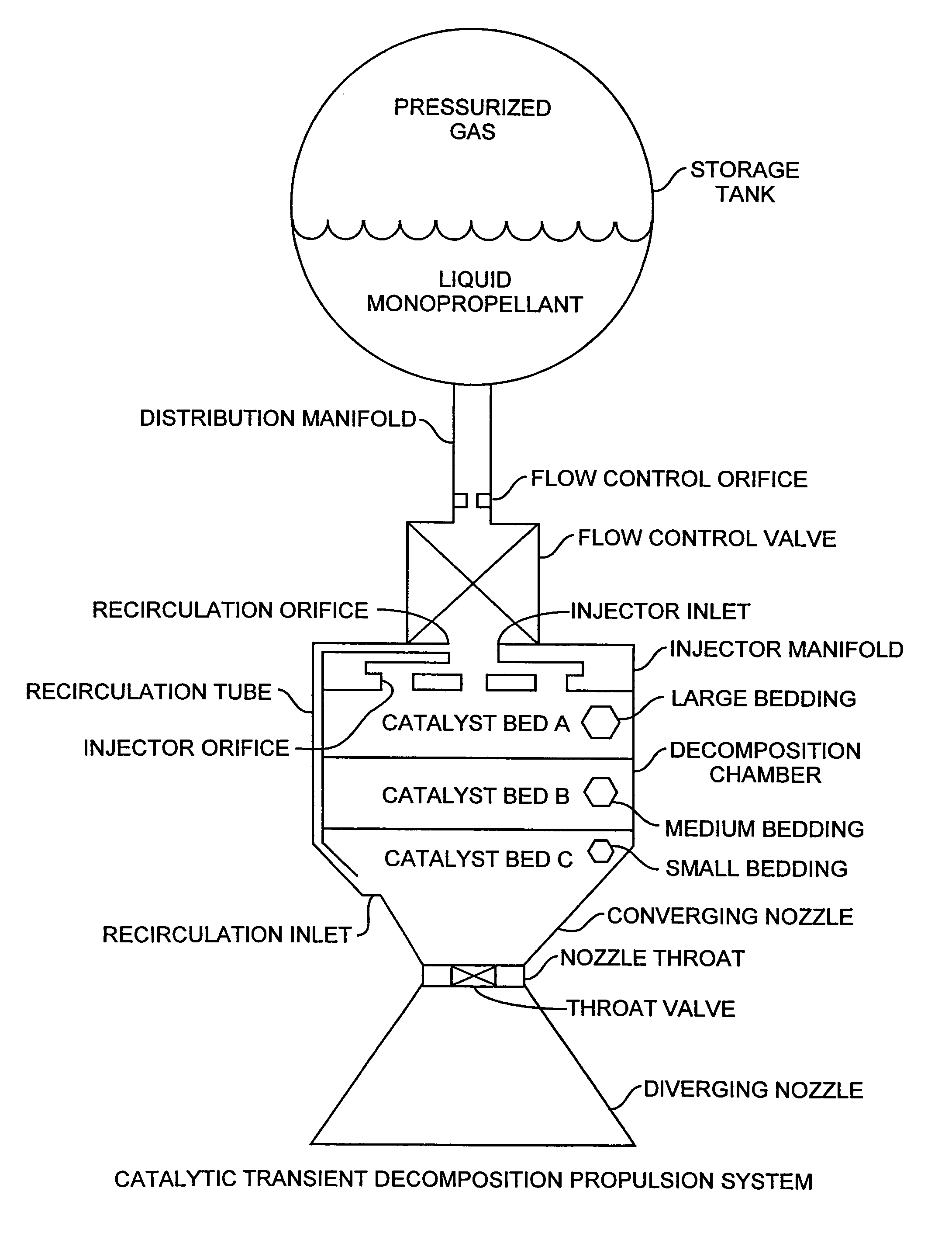
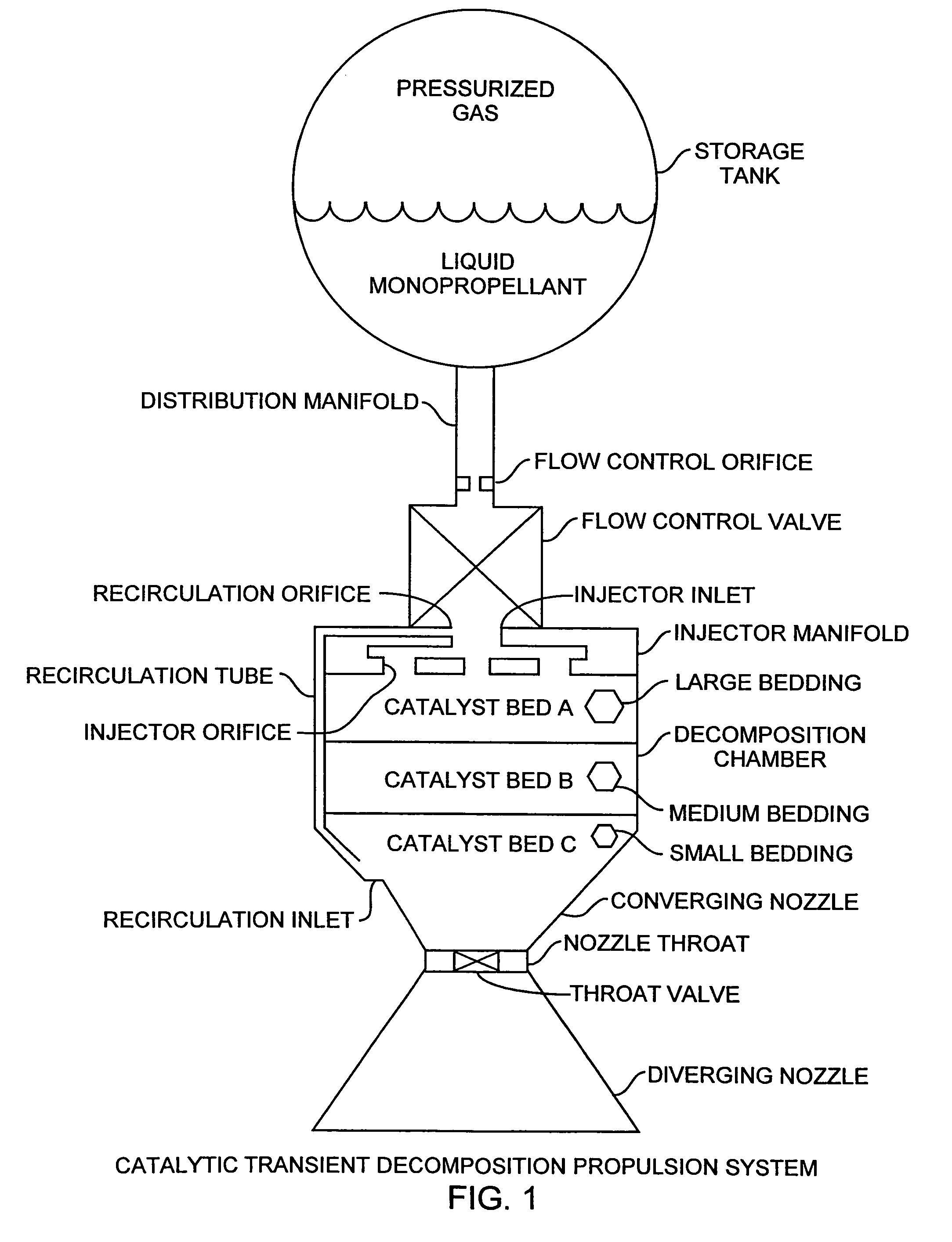
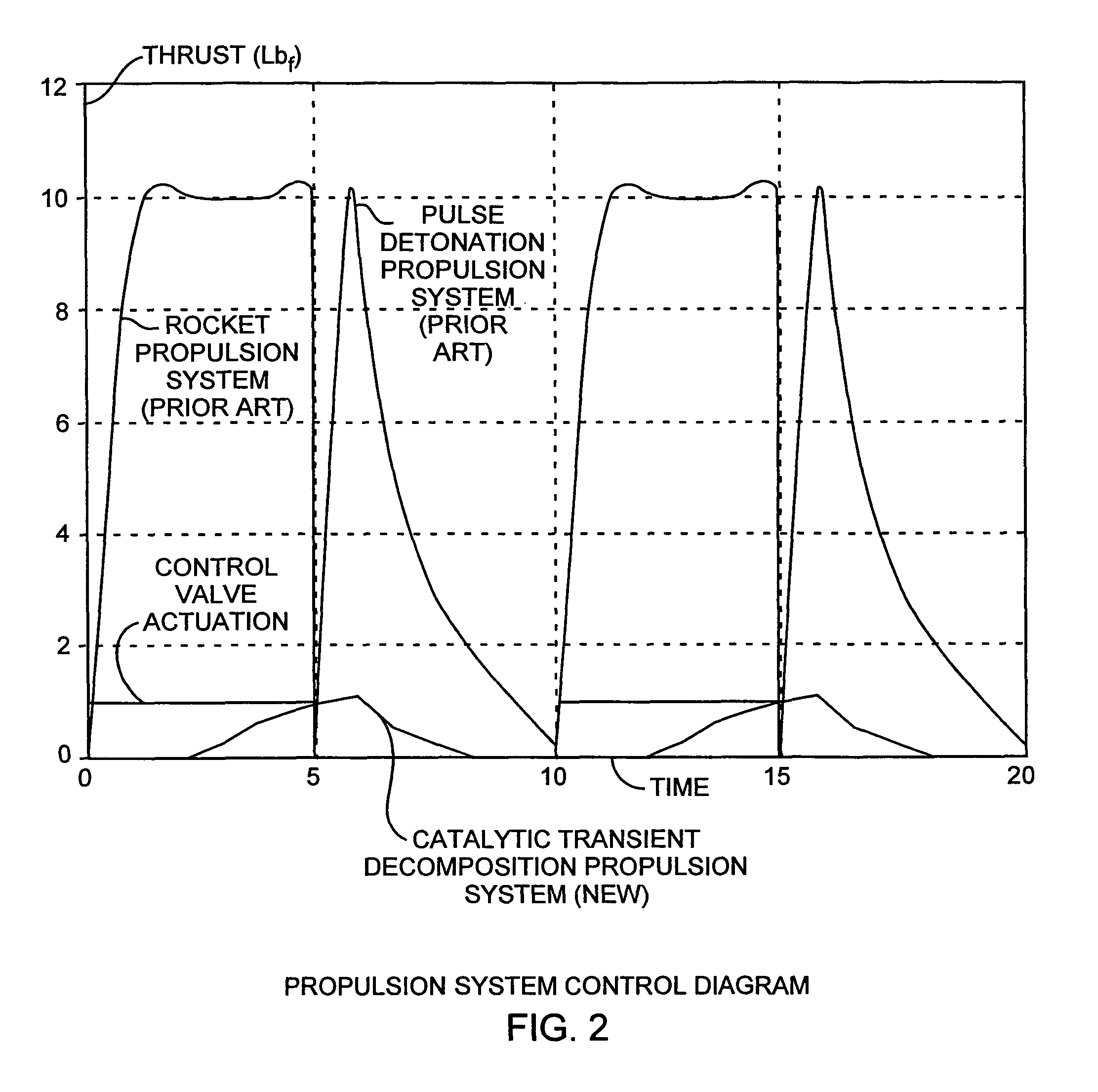
[0015]The invention is directed to a catalytically activated transient decomposition propulsion system that provides thrust by decomposing a monopropellant in contact with a catalyzing agent. The transient decomposition indicates that a majority of the monopropellant decomposition occurs after the intake control valve has closed in a catalytically activated decomposition propulsion system. The decomposition chamber pressure is transient in that, the chamber pressure rises when decomposition begins and the chamber pressure falls when all of the propellant is decomposed but never reaches a steady operating level. A fixed volume of liquid propellant is placed in contact with the catalyst within the decomposition chamber by a calibrated flow control valve for pulsing amounts of the monopropellant into the decomposition chamber. After injecting the liquid monopropellant into the decomposition chamber, the valve returns to the closed position. Surface tension holds the liquid monopropellant within the decomposition chamber until complete decomposition and exhaust of the warm gaseous products exhausted through a converging and diverging nozzle occurs. Thrust is produced by exhaust of the decomposed monopropellant, which had been slowly catalyzed after the liquid control valve was closed. Following the return to ambient pressure within the decomposition chamber, the valve control, propellant decomposition, and gaseous exhaust processes are repeated. In a preferred form, a throat valve and a recirculating tube are integral to the system for improved performance and control. The throat valve is used for improving the decomposition process leading to immediate usage of the decomposed gas within seconds. The recirculating tube provides for pressurized injection of the exhaust gas through the injector manifold to eliminate residue of unused liquid propellant. In the preferred form, the decomposition chamber is divided into a plurality of beds for supporting respective sized catalytic particles for providing a gradient of sized catalytic particles from the largest at the injector to the smallest at the converging nozzle for improved performance.
[0016]The improved density performance of the propulsion system increases the total ΔV available for the same sized system and therefore will allow a greater range of usable orbits. By allowing more orbital freedom, the propulsion system enables a wider range of useful payloads for picosatellite sized space vehicles. The propulsion system can provide sufficient thrust for small picospacecraft with the advantage of utilizing highly energetic but stable propellants such as hydroxyl ammonium nitrate (HAN). HAN is usable due to the slow decomposition process, which is insensitive to HAN's long ignition delay time and allows for greater heat transfer, mitigating HAN's high decomposition temperature. The propulsion system preferably uses HAN as a monopropellant to provide high total impulse in a safe manner. The use of HAN propellant allows simplified handling, storage, and test procedures due to the stability and nontoxicity of HAN for suitable use on picosatellites providing a successful, safe, and easily handled propulsion system capable of providing approximately five times greater total impulse. These and other advantages will become more apparent from the following detailed description of the preferred embodiment.

Problems solved by technology

Operations with rocket combustion require rapid ignition and high combustion temperature.
If ignition delay is too slow, unburned propellant will be exhausted from the rocket engine, reducing performance and potentially causing damage to the vehicle.
If combustion temperature is too high, materials within the combustion chamber will be degraded resulting in catastrophic failure of the engine.
This pressure spike creates design problems due to structural concerns with the combustion chamber and the transmission of the shock to the rest of the vehicle.
If a detonation could be generated by a catalyzed reaction, the force of the shock could damage the catalyst bed.
A solid propellant engine cannot completely close the throat exhaust valve because the combustion will either be completely extinguished and not reignited, or will accelerate resulting in a combustion chamber overpressure and rupture.
However, total available ΔV from the propulsion system has limited the orbits available to these vehicles.
With insufficient ΔV, the vehicles would be unable to perform sufficient deorbit maneuvers and could eventually create a hazard for other space vehicles.
The pressurized gas propulsion system is safe to use and requires only a simple exhaust system, but has low performance capability.
The primary concern is with hydrazine toxicity that creates severe handling and test restrictions that can add significant cost to the overall system.
These same handling concerns create safety issues when integrating the picosatellite with the primary payload on the launch vehicle.
The largest drawback of HAN usage is the difficulty rocket engines have had in achieving reliable, repeatable combustion ignition at reasonable preheat temperatures with catalysts that do not melt.
HAN ignition delay is too long for current conventional rockets and the HAN decomposition temperature is too high for current conventional catalysts.
Monopropellant catalytic decomposition engines for satellite propulsion systems using HAN cannot achieve short ignition delay times because the initial decomposition rate of liquid HAN is slow.
HAN is unsuitable for monopropellant catalytic decomposition engines because slowly decomposing HAN cannot decompose fast enough for sufficient engine efficiency and rapidly decomposing HAN results in excessively high temperatures, for example, greater than 2000° F., that are known to damage catalyst materials.
As such, HAN is not suitable for decomposition propulsion systems.
Two difficulties in designing a HAN based propulsion system are achieving the desired ignition characteristics and maintaining acceptable hardware temperatures during operation.

Method used


Image

  • Catalytically activated transient decomposition propulsion system
  • Catalytically activated transient decomposition propulsion system
  • Catalytically activated transient decomposition propulsion system

Examples


Embodiment Construction

[0019]An embodiment of the invention is described with reference to the figures using reference designations as shown in the figures. Referring to FIG. 1, a catalytic transient decomposition propulsion system includes a storage tank, pressurized gas and monopropellant that flows from the tank into a distribution manifold having a flow control orifice that restricts the flow to a maximum flow rate. The storage tank is a monopropellant holding tank that is pressurized by a compressing gas as the pressurized gas. The tank can be a low weight tank because a low pressure is sufficient to provide a low velocity liquid monopropellant injection. The pressurized gas can be nitrogen-compressed gas. The propellant is transported under pressure from the storage tank, through the distribution manifold and flow control orifice and through a flow control valve that controls the flow of the monopropellant through an injector inlet and into an injector manifold. The propellant flow control valve ope...


PUM


Abstract

A catalytically activated transient decomposition propulsion system provides thrust by decomposing flow controlled propellant in contact with a catalyzing agent using a fixed volume of liquid propellant that is placed in contact with the catalyst within the decomposition chamber by a calibrated flow control valve. After injecting the liquid propellant into the decomposition chamber, the valve returns to the closed position while surface tension holds the liquid within the decomposition chamber until complete decomposition and exhaust of the warm gaseous products through a converging and diverging nozzle occurs. The increasing and decreasing transient pressure in the decomposition chamber changes each cycle in response to flow control valve actuation as the decomposition process is repeated.

Description

FIELD OF THE INVENTION[0001]The invention relates to the field of propulsion systems. More particularly, the invention relates to catalytically activated decomposition propulsion systems.BACKGROUND OF THE INVENTION[0002]Rocket engines can be divided into four main categories consisting of ignition combustion engines, catalytic decomposition engines, pulsed detonation engines, and solid propellant engines. Ignition combustion engines are controlled by opening liquid propellant control valves and allowing propellants to flow into a combustion chamber. The combustion is either self-initiated due to a hypergolic reaction between propellants or by another ignition source, such as a spark plug. After combustion has begun, thrust is produced until the propellant control valves are closed and flow of propellant into the combustion chamber has stopped. The thrust level produced by combustion is directly related to the flow rate of propellants into the combustion chamber and therefore the pre...

Claims


Application Information

Patent Timeline
Patent Type & Authority Patents(United States)
IPC IPC(8): F02K9/44F02K9/68
CPCF02K9/50F02K9/58F02K9/68
Inventor COSTE, KEITH
Owner THE AEROSPACE CORPORATION
Why Eureka
Try Eureka