Particle-optical apparatus equipped with a gas ion source

a technology of gas ions and optical apparatus, which is applied in the field of particleoptical apparatus equipped with gas ions, can solve the problems of large chance of ions formation, limited processing speed of such ions, and interference of electric fields used in optics

Active Publication Date: 2010-08-10
FEI CO
View PDF21 Cites 26 Cited by
  • Summary
  • Abstract
  • Description
  • Claims
  • Application Information

AI Technical Summary

Benefits of technology

[0053]By now measuring the ion current, or at least a fixed portion hereof, and using this measured value to change a parameter that influences the ion production, it is possible to keep the current out of the ion source constant.
[0054]In

Problems solved by technology

The processing speed with such ion sources is limited by the ion current density in this ion spot.
The result of such a small exit diaphragm is that there is only a small volume at the vacuum side of the diaphragm wall where the gas pressure is so high as to result in a sizeable chance of the formation of ions.
However, as ions emerge from the ionization volume, the optics may spatially inter

Method used


Image

  • Particle-optical apparatus equipped with a gas ion source
  • Particle-optical apparatus equipped with a gas ion source
  • Particle-optical apparatus equipped with a gas ion source

Examples


Embodiment Construction

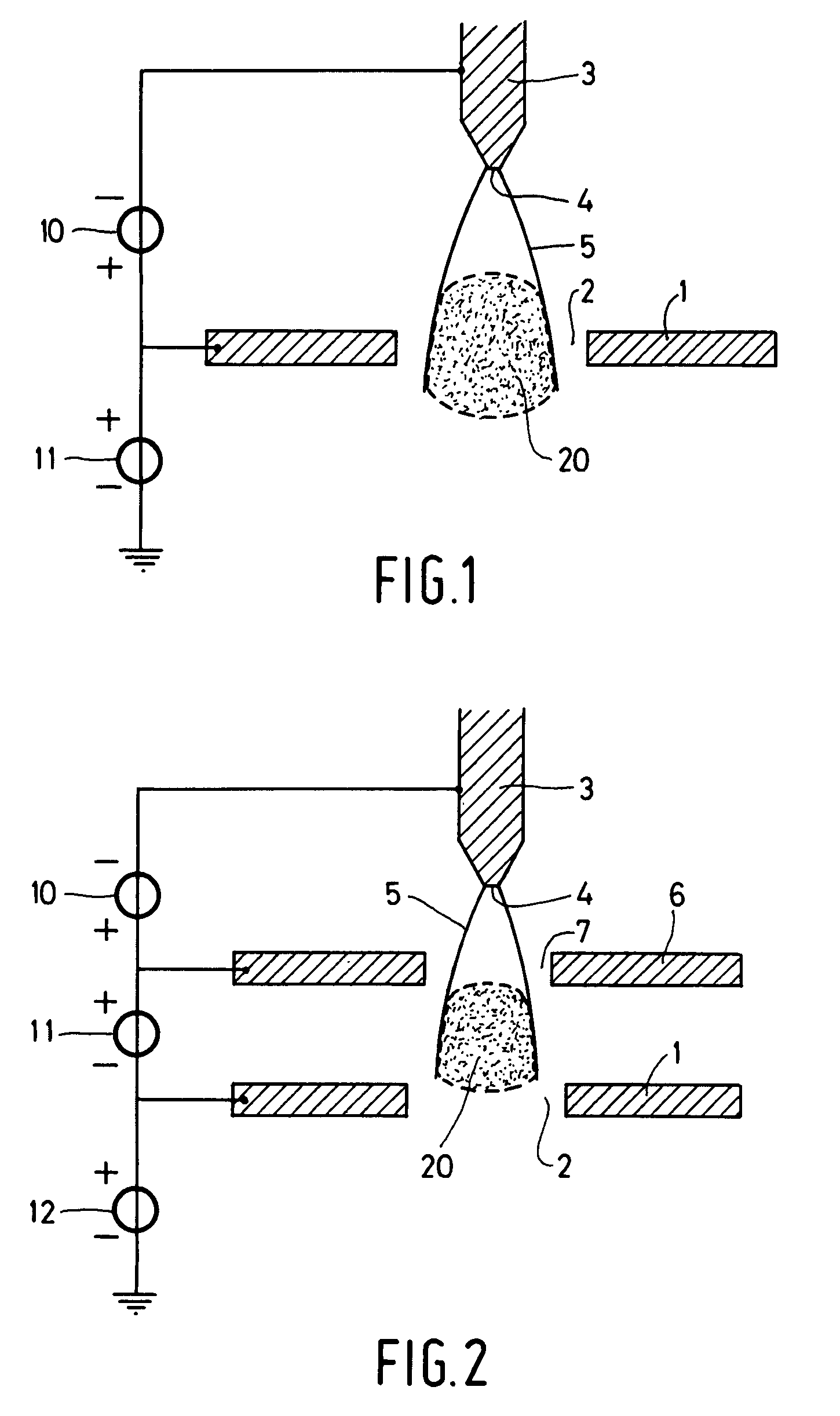
[0076]FIG. 1 shows an ion source according to the invention, whereby the electron-emitting surface 4 is located in the gas. The figure shows a diaphragm wall 1, with an exit diaphragm 2 therein. The size of the exit diaphragm 2 is smaller than 20 μm. Gas is admitted on one side of the diaphragm wall 1 at a pressure of, for example, 0.2 bar. On the other side, a vacuum, or at least a lower gas pressure, is maintained. As a result hereof, gas will flow out of the space where the gas is admitted, through the exit diaphragm 2, into the space where the vacuum is maintained. The diaphragm wall 1 is made of an electrically conductive material, such as a metal, or has conductive surfaces. In the direct vicinity of the exit diaphragm 2, there is located an electron source, such as a field emission source 3 with an electron-emitting surface 4. Between the field emission source 3 and the diaphragm wall 1, a potential difference is generated by a voltage source 10. As a result of this, a first ...


PUM


Abstract

The invention relates to an electron impact gas ion with high brightness and low energy spread. This high brightness is achieved by injecting electrons in a small ionization volume (from less than 1 μm to several tens of micrometers in size) from one side and extracting ions from the other. The electrons injected are produced by a high brightness electron source, such as a field emitter or a Schottky emitter.
In one embodiment of the invention the required high electron density in the ionization volume is realized by placing a field emitter close to the ionization volume (e.g. 30 μm), without optics between source and ionization volume.
In another embodiment of the invention the source is imaged onto a MEMS structure. Two small diaphragms of e.g. 50 nm are spaced e.g. 1 μm apart. The electrons enter through one of these diaphragms, while the ions leave the ionization volume through the other one. The two diaphragms are manufactured by e.g. drilling with an ion beam, resulting in two small and well aligned diaphragms.

Description

TECHNICAL FIELD OF THE INVENTION[0001]The invention relates to a particle-optical apparatus equipped with a gas ion source, which gas ion source comprises a diaphragm wall in which an exit diaphragm with a diameter of at most 20 μm is fitted, an electron source with an electron-emitting surface for generating an electron beam, gas admittance means for admitting a gas at a first side of the diaphragm wall, vacuum means for causing a vacuum—in the form of a lower gas pressure—at the other side of the diaphragm wall, acceleration means for producing an acceleration field accelerating the electron beam to an energy whereby the electrons of this electron beam ionize the gas in an ionization volume, and extraction means for producing an extraction field extracting the produced gas ions from the ionization volume.[0002]The invention also relates to a gas ion source for application in such an apparatus. A gas ion source for such an apparatus is known from U.S. Pat. No. 4,500,787.BACKGROUND ...

Claims


Application Information

Patent Timeline
IPC IPC(8): H01J27/02
CPCH01J27/205H01J37/08H01J2237/082H01J2237/0807
Inventor KRUIT, PIETERTONDARE, VIPIN NAGNATH
Owner FEI CO
Why Eureka
Try Eureka