Electrospray neutralization process and apparatus for generation of nano-aerosol and nano-structured materials

a technology of electrostatic neutralization and nano-structured materials, which is applied in the direction of separation of raw materials, filtration separation, and separation of processes, etc., can solve the problems of inability to apply the method of manufacturing nano-aerosols from most polymer and biological molecules, and the stability of highly charged aerosols created by es, and the currents in the atomizer and the neutralizing corona to control the neutralization have not been measured independently, so as to achieve low pri

Inactive Publication Date: 2010-08-17
GEORGE MASON INTPROP INC
View PDF2 Cites 12 Cited by
  • Summary
  • Abstract
  • Description
  • Claims
  • Application Information

AI Technical Summary

Problems solved by technology

However, this method cannot be applied for manufacturing nano-aerosols from most polymer and biological molecules, as well as for organisms.
Although ES has been used to create monodisperse aerosols [De La More, et al., (1990)], stability of highly charged aerosols created by ES is low.
However, even though these processes have shown in some partial neutralization of aerosol, currents in the atomizer and the neutralizing corona to control neutralization have not been measured independently.
Both these neutralization techniques suffer one obvious limitation when applied to production of biological aerosols.
Being highly reactive these products are capable of breaking covalent bonds and producing deep chemical modification, which may result in inactivation of fragile biological molecules and the killing of cells, spores, and viruses.
Another limitation among known neutralization techniques involves the exclusive use of small counter ions.
Moreover, the prior art does not consider any applications connected with either the formation of biological aerosols or biological applications of such aerosols.
Evaporation may cause the droplets to lose their stability and disintegrate.
This solution tends to be unstable, since molecules may adsorb on walls of the chamber and aggregate.
In many cases, formation of dry nano-aerosol can start with formation of charged micron-sized solution droplets, which may further evaporate and decay upon reaching the Rayleigh limit of electrostatic stability.
Since only ethanol ions and clusters were charged negatively in this experiment their capturing was not likely possible due to high volatility of ethanol.
However, this known mechanism of neutralization may present certain limitations.
A consequence of this neutralization mechanism is the substantially higher deposition of fibers in the areas adjacent to the conducting support, which tends to leave remotely positioned areas of the network not only poorly populated with fibers, but also transparent to aerosol.
Such gluing may result in a nano-filter.
The lack of a compression mechanism schematized in FIG. 17 may result in fiber ends and trains of fibers protruding outside, making its surface appear “wooly.” Cleaning such nano-mat or nano-filter from dust particles may be more difficult as compared with those fabricated using the technology visualized in FIG. 15B.
A problem that may arise concerns the contradictory requirement of stability at high humidity with solubility in water solutions.
However, limitations may also exist.
Such result is of practical importance, since formation of a fibrous aerosol due to nano-filter failure would likely create a problem of human protection from such aerosol.
When nano-mats are glued to the mesh, as exemplified in Frame B of FIG. 31, a complete failure is not likely to be reached.
One potential problem that might be encountered in cross-linking with both epoxy and with photo-adhesives is incomplete solidification.
This procedure is expected to result in self-gluing between contacting nano-fibers.
This simple design has one major drawback when applied to electrospinning of polymer solutions.
Parts of the solution dried at the tip tend to cause clogging.
This dry deposit may change the electrospinning conditions, and may also completely stop the spinning process.
Testing this spinneret with a 10% CA solution showed that it may also suffer from tip fouling with dried polymer.
No dry deposit was observed upon electrospinning of this solution, which is particularly prone to formation of dry deposits due to the high volatility of acetone.

Method used


Image

  • Electrospray neutralization process and apparatus for generation of nano-aerosol and nano-structured materials
  • Electrospray neutralization process and apparatus for generation of nano-aerosol and nano-structured materials
  • Electrospray neutralization process and apparatus for generation of nano-aerosol and nano-structured materials

Examples


example 1

A. Example 1

Formation of a PVP Aerosol

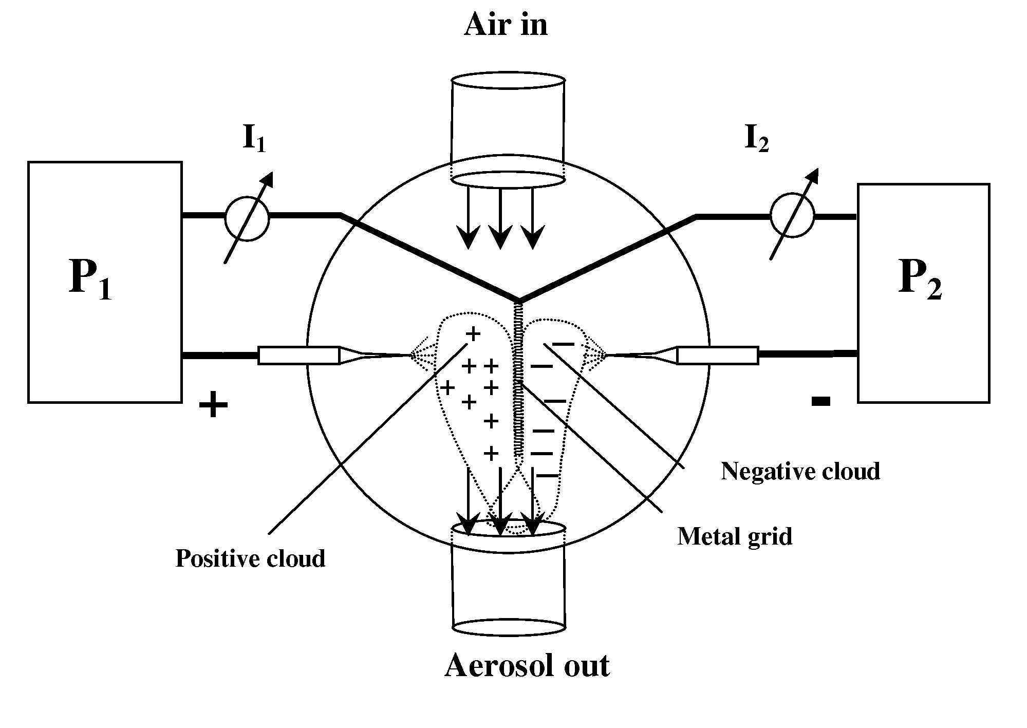
[0240]In this example, 10 μL of 5% PVA solution in water was loaded into the capillary connected to the positive potential. A 50% ethanol solution was placed into the opposite capillary to neutralize the cloud of PVA particles. At a voltage of about 6-about 8 kV and a current of about 30-about 50 nA, an aerosol cloud was formed in seconds. The aerosol cloud was readily observed by passing a laser beam through the chamber. Unlike charged aerosol clouds, which disappeared in ˜2 to ˜5 sec after switching off the power, it was found that the neutral aerosol was still visible within the chamber up to about 10 to about 15 min after the voltage was disconnected. Such stability is a strong indicator of aerosol neutrality. In contrast to charged aerosols, particles in a neutral aerosol cloud are much less prone to interactions with chambers walls and are less likely to deposit there.

[0241]Since neutral aerosols decays in ˜10 min, one can estimate the sta...

example 2

B. Example 2

Deposition of Aerosol on Chamber Walls

[0243]In this example, 10 μL of 0.5% methylene blue dye in 50% ethanol was electrosprayed at the positive potential against negatively sprayed 50% glycerol at a voltage of about 6-about 9 kV and a current of about 0.7-about 1 μA. The glycerol droplets formed a readily visible aerosol. Approximately 1 mL of water was then placed into the chamber; the water was moved over the walls to collect the deposited dye. When the OD of the dye was measured at ˜608 nm relative to the wall area from which the aerosol was collected, it was found that about twice as much aerosol was deposited at the chamber bottom as compared to the top. Deposition on vertical walls was intermediate between the top and the bottom values. Such difference in deposition can be explained by the relatively large size of the aerosol (approximately more than 1 μm), which may be subjected to gravitational force.

example 3

C. Example 3

Formation of Molecular Nano-aerosol

[0244]In this example 0.05% PVP solution in water was electrosprayed from a positively charged capillary against pure ethanol electrosprayed from a negatively charged capillary. In contrast to the experiment described in Example 1, no visible aerosol was apparently seen upon illumination the chamber with a laser beam. However, freshly cleaved mica placed at the bottom of the chamber for ˜5 min was covered with dots at approximately 2.3±0.6 nm high, as seen in FIG. 37. The density of dots was about 10 particles per square μm. It was estimated that the height corresponds to a hemisphere comprising a single polymer molecule with an average mol. mass of 200 kDa. The average surface density of the nano-particles deposited on mica in T=5 min was measured as N=10 particles per square micron. With the diffusion coefficient expected for such particles in the air (D=˜10−3 cm2 / sec) and the thickness of an unstirred layer over mica surface (H=1 cm)...


PUM

PropertyMeasurementUnit
diameteraaaaaaaaaa
volumesaaaaaaaaaa
volumesaaaaaaaaaa

Abstract

The claimed invention describes methods and apparatuses for manufacturing nano-aerosols and nano-structured materials based on the neutralization of charged electrosprayed products with oppositely charged electrosprayed products. Electrosprayed products include molecular ions, nano-clusters and nano-fibers. Nano-aerosols can be generated when neutralization occurs in the gas phase. Neutralization of electrospan nano-fibers with molecular ions and charged nano-clusters may result in the formation of fibrous aerosols or free nano-mats. Nano-mats can also be produced on a suitable substrate, forming efficient nano-filters.

Description

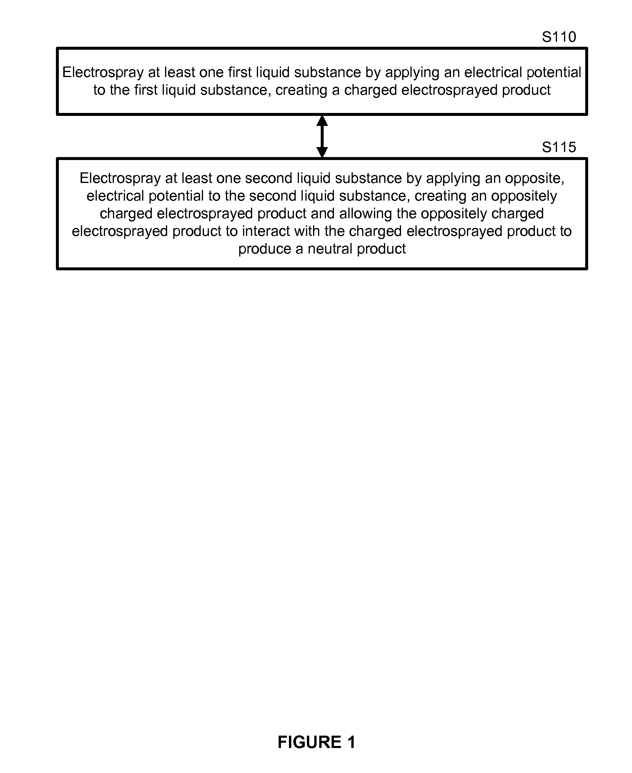
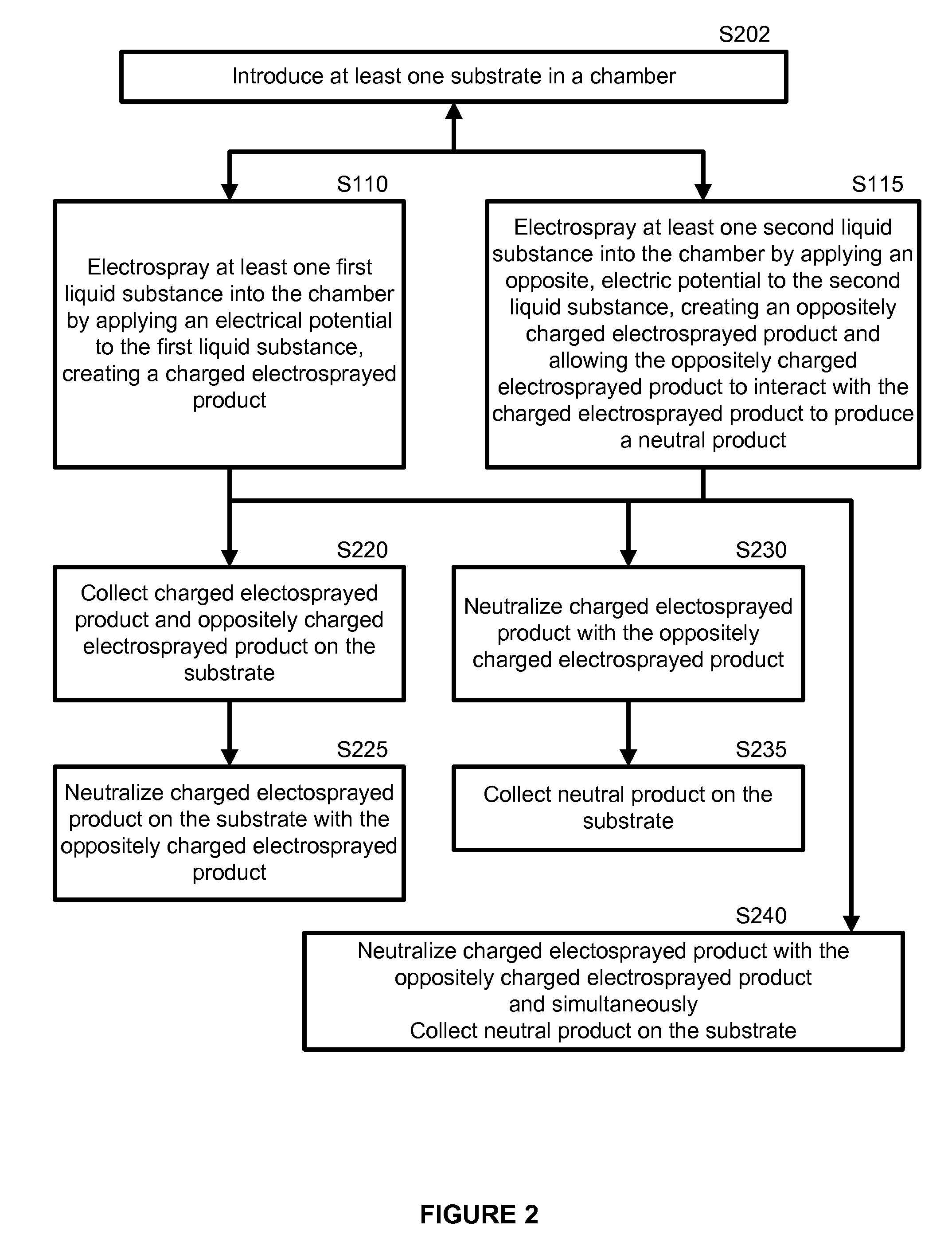
CROSS REFERENCE TO RELATED APPLICATIONS[0001]The present application claims the benefit of provisional patent application Ser. No. 60 / 737,392 to Morozov et al., filed on Nov. 17, 2005, entitled “Electrospray Neutralization Method and Apparatus for Nano-Aerosol Manufacturing,” which is hereby incorporated by reference.GOVERNMENT LICENSE RIGHTS TO CONTRACTOR-OWNED INVENTIONS MADE UNDER FEDERALLY SPONSORED RESEARCH AND DEVELOPMENT[0002]This invention was made with government support under Grant No. DE-F C52-04NA25455 awarded by the United States Department of Energy. The government has certain rights in the invention.BRIEF DESCRIPTION OF THE DRAWINGS[0003]FIG. 1 shows an example of a flow diagram for producing nano-aerosols and nano-structured materials.[0004]FIG. 2 shows another example of a flow diagram for producing nano-aerosols and nano-structured materials.[0005]FIG. 3 shows yet another example of a flow diagram for producing nano-aerosols and nano-structured materials.[0006]FIG....

Claims


Application Information

Patent Timeline
Patent Type & Authority Patents(United States)
IPC IPC(8): B05D1/04
CPCB01D39/1623B01D46/0001B01D46/10D01D5/0007B01D2239/0435B01D2275/10
Inventor BAILEY, CHARLES L.MOROZOV, VICTORVSEVOLODOV, NIKOLAI N.
Owner GEORGE MASON INTPROP INC
Why Eureka
Try Eureka