Method for maskless particle-beam exposure

a technology of maskless and particle beams, applied in the field of maskless particle beam exposure, can solve the problems of many orders of magnitude of failure of current architectures in these two aspects

Active Publication Date: 2010-08-17
IMS NANOFABTION
View PDF44 Cites 104 Cited by
  • Summary
  • Abstract
  • Description
  • Claims
  • Application Information

AI Technical Summary

Benefits of technology

[0009]The present invention provides a method which offers high throughput rates in combination with a PD design that is easy to implement to overcome the deficiencies of the prior art.
[0011]The invention offers a writing strategy that offers an optimal writing speed over the target and lends itself to an electronic layout which is realizable using standard CMOS technologies and allows a simplified realization of the blanking circuitry in the PD means.
[0012]The invention provides a PD device for electron beam writing which makes it possible to write with the speed only limited by the e-beam density and the APS transitivity. Power consumption and data rate to the APS can be handled within the UMC 0.25 μm process. Currently used architectures would fail in these two aspects by many orders of magnitude.
[0015]Furthermore it is advantageous if outside of said pixel exposure periods the patterned beam is blanked out in a manner that it does not reach the target, but is absorbed at an absorbing means before it can reach the target.
[0026]A particular advantage is that the target positioning method and a subsequent particle-beam exposure exposure / irradiation process performed on the target can employ the same pattern definition means with the target moving relatively to the pattern definition means in a corresponding manner. However, the distance of advance of the target positioning method may be larger than that during the particle-beam exposure / irradiation process.

Problems solved by technology

Currently used architectures would fail in these two aspects by many orders of magnitude.

Method used


Image

  • Method for maskless particle-beam exposure
  • Method for maskless particle-beam exposure
  • Method for maskless particle-beam exposure

Examples


Embodiment Construction

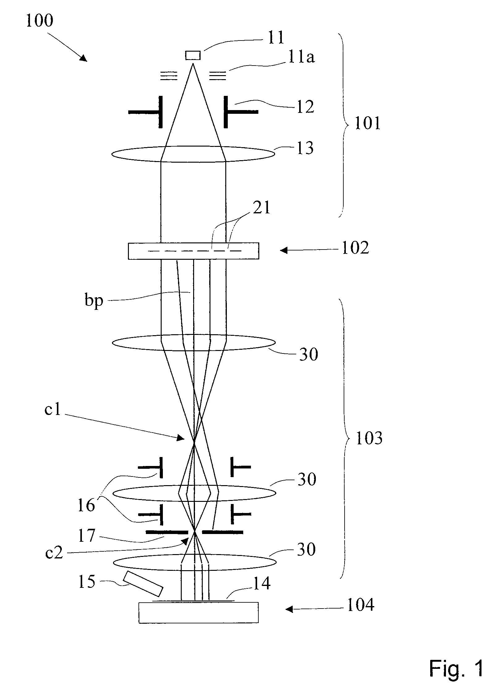
[0046]The preferred embodiment of the invention discussed in the following is a development from the PML2-type particle-beam exposure apparatus with a pattern definition (PD) system as disclosed in the U.S. Pat. No. 6,768,125 (=GB 2 389 454 A) of the assignee / applicant, and with a large-reduction projecting system. In the following, first the technical background of the apparatus is rendered as far as relevant to the invention, then embodiments of the invention are discussed in detail. It should be appreciated that the invention is not restricted to the following embodiments or the particular layout of PD system, which merely represent one of the possible implementations of the invention; rather, the invention is suitable for other types of processing systems that employ a particle-beam with projection stages as well.

PML2 System

[0047]A schematic overview of a maskless particle-beam processing apparatus PML2 employing the invention is shown in FIG. 1. In the following, only those det...


PUM


Abstract

For maskless irradiating a target with a beam of energetic electrically charged particles using a pattern definition means with a plurality of apertures and imaging the apertures in the pattern definition means onto a target which moves (v) relative to the pattern definition means laterally to the axis, the location of the image is moved along with the target, for a pixel exposure period within which a distance of relative movement of the target is covered which is at least a multiple of the width (w) of the aperture images as measured on the target, and after said pixel exposure period the location of the beam image is changed, which change of location generally compensates the overall movement of the location of the beam image.

Description

FIELD OF THE INVENTION AND DESCRIPTION OF PRIOR ART[0001]The invention relates to an improved method for irradiating a target with a beam of energetic electrically charged particles, wherein a pattern definition means having a plurality of apertures transparent to said particles is used, and by illuminating said pattern definition means with said beam, which traverses the pattern definition means through said apertures, a patterned beam is formed consisting of a corresponding plurality of beamlets, and said patterned beam is formed into an image on the location of the target, said image comprising the images of at least part of the plurality of apertures; the aperture images have a first width, wherein said target moves relative to the pattern definition means along a path within an image plane in which the images of apertures are formed (or in a direction generally perpendicular to a propagation direction of the patterned beam).[0002]A method of this kind and the pertinent particle...

Claims


Application Information

Patent Timeline
Patent Type & Authority Patents(United States)
IPC IPC(8): H01J49/00
CPCB82Y10/00B82Y40/00H01J37/302H01J37/3174H01J2237/30483
Inventor FRAGNER, HEINRICHPLATZGUMMER, ELMAR
Owner IMS NANOFABTION
Why Eureka
Try Eureka