
Digital phase locked loop with gear shifting

a technology of phase lock and gear shifting, applied in the field of control system and data communication, can solve the problems of inability to cost effectively add features and reduce footprint, the immaturity of advanced processes, and design challenges that may outweigh the intended advantage,

Active Publication Date: 2010-08-17
TEXAS INSTR INC
View PDF10 Cites 39 Cited by
  • Summary
  • Abstract
  • Description
  • Claims
  • Application Information

AI Technical Summary

Benefits of technology

The present invention relates to a method for estimating the modulation gain of an RF oscillator in a cellular telephone handset. This is important for accurate knowledge of the phase locked loop and transmit frequency modulation path, which can impact the performance of the handset. The invention proposes an all-digital frequency synthesizer architecture built around a digitally controlled oscillator that is tuned in response to a digital tuning word. The invention also includes a phase detection mechanism, a time-to-digital converter, and a sample rate converter for data resampling. The technical effects of the invention include improved accuracy in estimating the modulation gain of the RF oscillator, reduced complexity and cost of the design, and improved performance of the phase locked loop.

Problems solved by technology

However, for analog / RF designs, the immaturity of advanced processes comes with design challenges that may outweigh the intended advantage.
In a typical handset, 30 to 40% of handset board space is occupied by analog / RF functionality which cannot be re-designed or migrated to the newer process / technology nodes easily, inhibiting vendor ability to cost effectively add features and reduce footprint.

Method used


Image

  • Digital phase locked loop with gear shifting
  • Digital phase locked loop with gear shifting
  • Digital phase locked loop with gear shifting

Examples


case i

[0127]For the case of a type-II PLL, when the loop filter 1140 is a simple PI controller, the filtered phase error φf(t) is given by

[0128]ϕf⁡(t)=α⁢⁢ϕe⁡(t)+ρ⁢∫t⁢ϕe⁡(τ)⁢⁢ⅆτ(10)

where α and ρ are the proportional and integral gains of the controller In frequency domain, the loop filter transfer function is

[0129]H⁡(s)=ϕF⁡(s)ϕE⁡(s)=α+ρs(11)

[0130]With the oscillator 1142 being represented by a simple integrator, i.e.,

[0131]O⁡(s)=1s,

we can write the PLL transfer function as

[0132]G⁡(s)=⁢H⁡(s)⁢O⁡(s)1+H⁡(s)⁢O⁡(s)=⁢(α+ρs)·1s1+(α+ρs)·1s=⁢s⁢⁢α+ρs2+s⁢⁢α+ρ(12)

Comparing the dominator with a generic 2nd order system transfer function, we have

s2+sα+ρ==s2+2ζωns+ωn2

Comparing co-efficients, we get

2ζωn=α

ωn2=ρ  (13)

and simplifying the relations along with the standard relation for frequency response of a 2nd order system

ω=ωn·√{square root over (1−ζ2)}  (14)

we have

[0133]ωn=ρ⁢⁢ζ=α2·ρ⁢⁢ω=ρ-α24(15)

Therefore, for the simple PLL, the settling time of the system is given by

[0134]ts=4ζ⁢⁢ωn=8α(16)

[0135]It is evide...

case ii

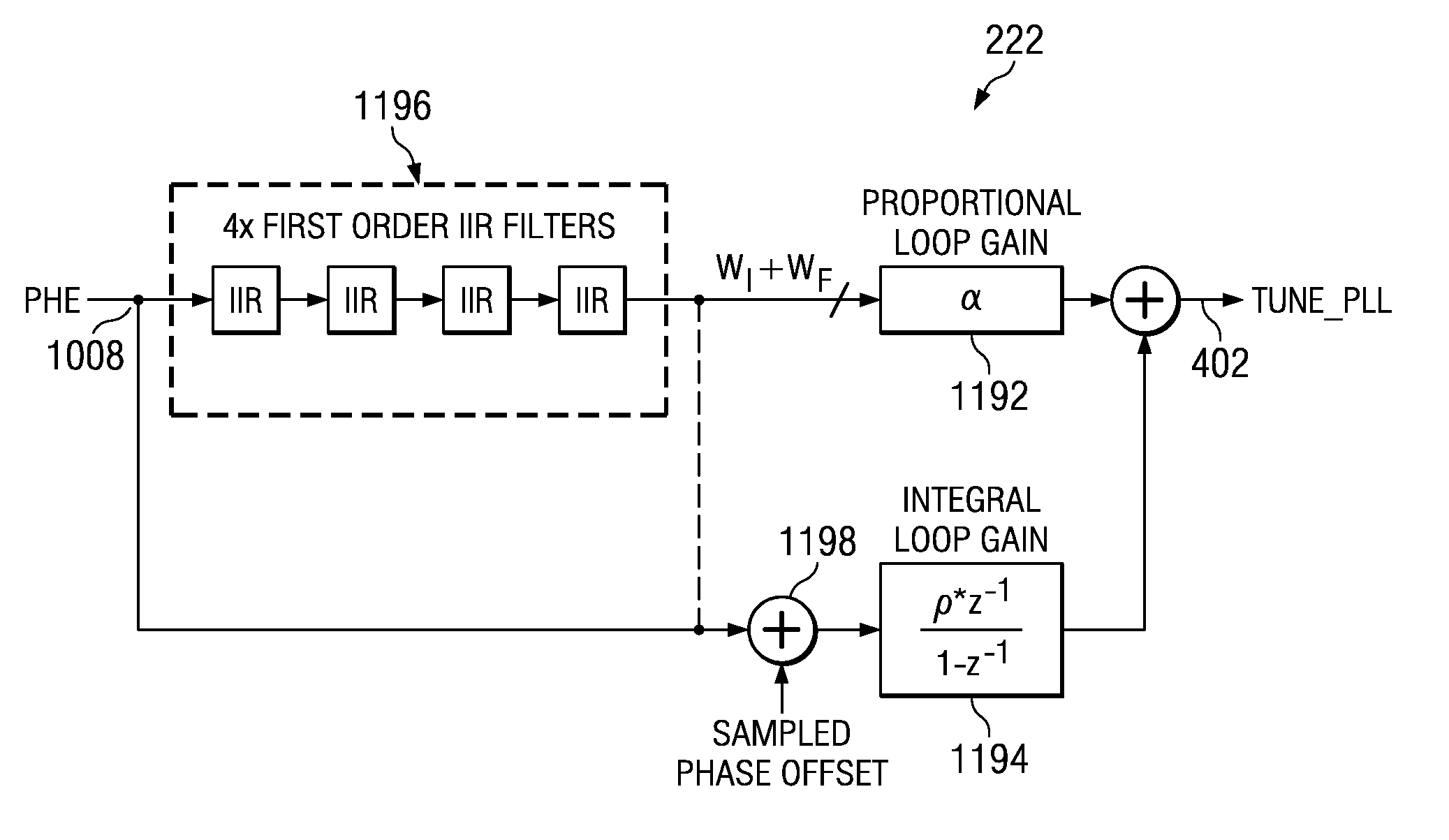
[0136]For the case of a type-II PLL, when the loop filter comprises a set of filters followed by a PI controller, as illustrated in 11A, The z-domain transfer function of the ADPLL loop filter 222 is given by

[0137]H⁡(z)=α⁢⁢F⁡(z)+ρ⁢⁢z-11-z-1(17)

where α and ρ are the proportional and integral gains of the controller and F(z) is the transfer function of the IIR filters given by

[0138]F⁡(z)=∏i=03⁢⁢λi1+(1-λi)⁢z-1(18)

[0139]In s-domain, the corresponding loop filter transfer function is

[0140]H⁡(s)=ϕF⁡(s)ϕE⁡(s)=α⁢⁢F⁡(s)+ρs(19)

where F(s) is the s-domain equivalent transfer function of the IIR filters. Therefore, the ADPLL transfer function becomes

[0141]G⁡(s)=s⁢⁢α⁢⁢F⁡(s)+ρs2+s⁢⁢α⁢⁢F⁡(s)+ρ(20)

[0142]Comparing the denominator with a generic 2nd order system transfer function, we have

s2+sαF(s)+ρ==s2+2ζωns+ωn2

[0143]Comparing coefficients, and simplifying we get the following relations for the ADPLL dynamics

[0144]ωn=ρ⁢⁢ζ=α⁢⁢F⁡(s)2·ρ⁢⁢ω=ρ-α2⁢F⁡(s)24(21)

[0145]Therefore, for the simple PLL, the settli...

case b

hifting of PI Controller's Proportional Gain

[0186]The table 4 shows the impact of gear-shifting the proportional gain α down by one step. The impact is a big increase in the ADPLL loop BW, accompanied with a sharp decline in the gain and the phase margin of the system

[0187]

TABLE 40 dB CLGainPhaseBWMarginMarginlambda1lambda2lambda3lambda4alpharho[kHz][dB][deg]3445615125.9911.2944.343445515211.645.7828.74

Case C: Gear-Shifting of PI Controller's Integral Gain

[0188]The table 5 shows the impact of gear-shifting the integral gain ρ up by one step. The impact is a decrease in the ADPLL loop BW, accompanied by an increase in the gain and the phase margin of the system

[0189]

TABLE 50 dB CLGainPhaseBWMarginMarginlambda1lambda2lambda3lambda4alpharho[kHz][dB][deg]3445615125.9911.2944.343445616112.4911.8050.69

Case D: Simultaneous Gear-Shifting of the PI Controller's Proportional and Integral Gains

[0190]As per eq. (15), if we neglect the contribution of the IIR filters, the ADPLL frequency damping...


PUM


Abstract

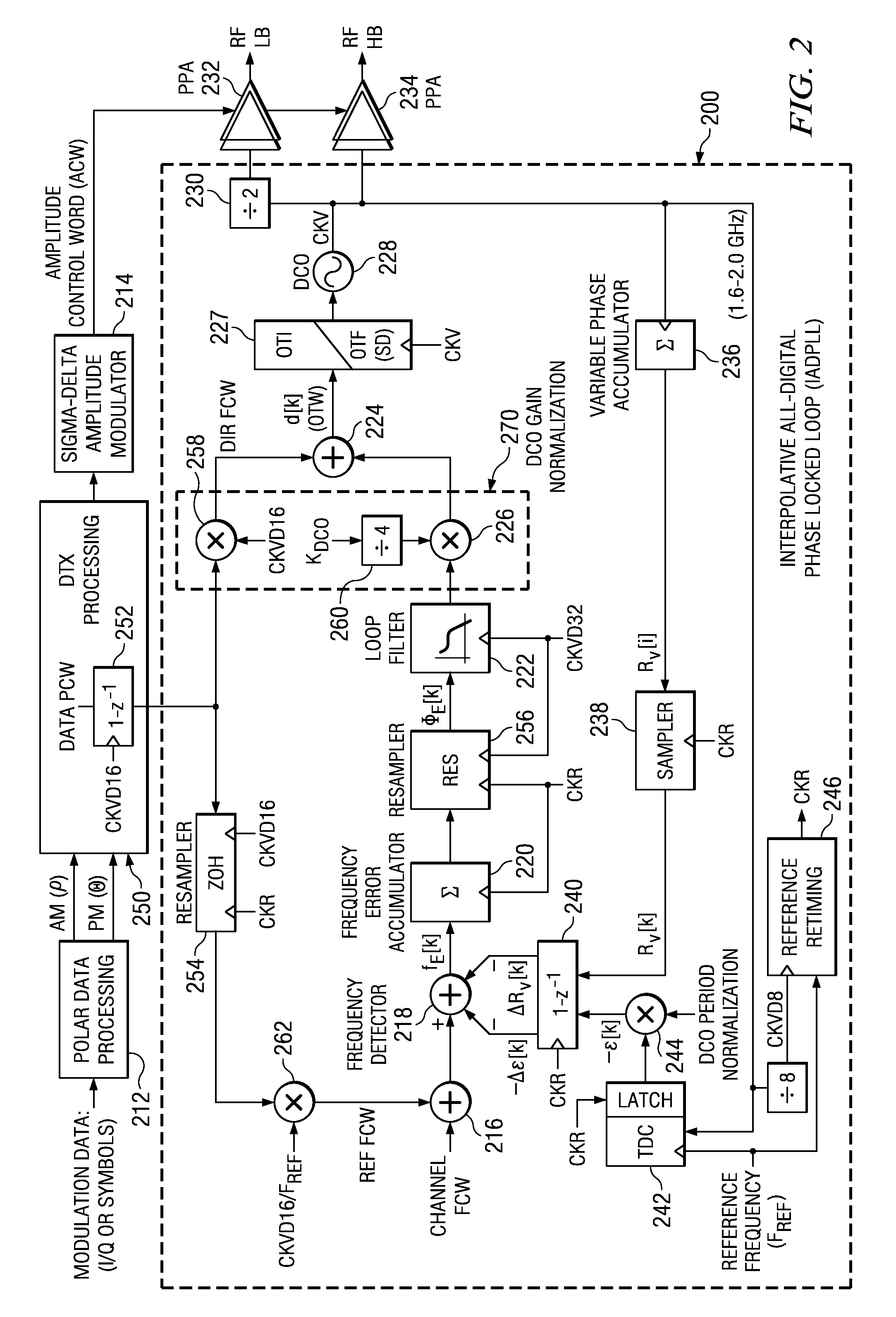
An embodiment of the present invention provides a phase locked loop that operates on clock signals derived from an RF clock signal generated by the phase locked loop. A frequency reference input provides a reference clock. A controllable oscillator generates the RF clock signal. A phase detection circuit operates on the reference clock to provide digital phase error samples indicative of a phase difference between the reference clock and the RF clock. A programmable filter is connected to receive the phase error samples and connected to provide a filtered output having a gain and a phase margin to the controllable oscillator. The programmable filter includes a proportional loop gain control having a programmable loop gain coefficient (alpha—α) and an integral loop gain control having a programmable loop gain coefficient (rho—ρ). Alpha and rho are configured to be programmatically changed simultaneously and are selected such that the gain is changed and the phase margin remains substantially unchanged.

Description

CLAIM OF PRIORITY UNDER 35 U.S.C. 119(E) AND 35 USC 120[0001]The present application claims priority to and incorporates by reference U.S. Provisional Application No. 60 / 945,818 filed Jun. 22, 2007, entitled “Interpolative All-Digital Phase Locked Loop”. The present application also claims priority to U.S. application Ser. No. 11 / 551,050 filed Oct. 19, 2006 and entitled “CONTINUOUS REVERSIBLE GEAR SHIFTING MECHANISM”FIELD OF THE INVENTION[0002]This invention generally relates to the field of control systems and data communications. In particular, it relates to cellular telephony and communication devices such as Bluetooth, WLAN, etc. using all-digital radio frequency (RF) circuitry.BACKGROUND OF THE INVENTION[0003]With each successive cellular phone handset generation, users demand more features in a smaller form factor. Some recent examples include cell phones with integrated Bluetooth, GPS, digital camera, and MP3 functionality. Process shrinks help deliver a cost and size advanta...

Claims


Application Information

Patent Timeline
Patent Type & Authority Patents(United States)
IPC IPC(8): H03L7/093H03L7/16
CPCG04F10/005H03L7/091H03L7/0991H03M1/0639H04L27/0014H03L2207/50H03M1/12H04L5/0007H04L27/2657H04L2027/0016H04L2027/0051H04L2027/0055H04L2027/0067H04L2027/0069H04L2027/0097
Inventor WAHEED, KHURRAMWALLBERG, JOHNSTASZEWSKI, ROBERT BOGDANVEMULAPALLI, SUDHEER
Owner TEXAS INSTR INC
Learn More