Metal complex compound and organic electroluminescent element using the same

a technology of metal complex compound and organic electroluminescent element, which is applied in the direction of solid-state device, discharge tube/lamp details, indium organic compound, etc., can solve the problem of extremely poor heat resistance and achieve the effect of long life and high light emission efficiency

Inactive Publication Date: 2010-08-24
IDEMITSU KOSAN CO LTD
View PDF14 Cites 1 Cited by
  • Summary
  • Abstract
  • Description
  • Claims
  • Application Information

AI Technical Summary

Benefits of technology

[0006]The present invention has been made to overcome the above problems and has an objective of providing an organic EL device having a high efficiency of light emission and a long lifetime, and also a novel metal complex compound for producing the organic EL device.
[0023]The present invention provides an organic EL device having a high efficiency of light emission and a long lifetime, and also a novel metal complex compound for producing the organic EL device.THE PREFERRED EMBODIMENT TO CARRY OUT THE INVENTION
[0076]In the organic EL device of the present invention, it is preferable that the light emitting layer comprises a metal complex compound of the present invention as the light emitting material. In general, the light emitting layer is formed as a thin layer in accordance with the vacuum vapor deposition process or the coating process. It is preferable that the layer comprising the metal complex compound of the present invention is formed as a thin layer in accordance with the coating process since the production process can be simplified by using the coating process.
[0129]In addition, it is preferable to employ an inorganic compound of insulator or semiconductor as a material constituting an electron injecting or transporting layer in the organic EL device of the present invention. When the electron injecting or transporting layer comprises the above insulator or semiconductor, it is possible to prevent the leakage of the electric current effectively and the electron injecting capability can be improved. It is preferable that at least one metal compound selected from the group consisting of alkali metal chalcogenides, alkaline earth metal chalcogenides, alkali metal halides and alkaline earth metal halides is used as the insulator. It is preferable that the electron injecting or transporting layer comprises the above alkali metal chalcogenide and the like since the electron injecting capability can be improved.
[0132]In addition, at least any one of the electron injecting layer and electron transporting layer of the organic EL device of the present invention may contain a reductive dopant with the work function of 2.9 eV or less. In the present invention, the reductive dopant means compounds which increase the electron injecting efficiency.
[0133]Further, it is preferable in the present invention that a reductive dopant is added into an interface area between the cathode and the organic thin film layer. The dopant reduces at least one part of the organic layer contained in the interface area to form anion. Preferable examples of the reductive dopant include at least one compound selected from the group consisting of alkali metals, alkali metal oxides, alkaline earth metals, rare earth metals, alkali metal oxides, alkali metal halides, alkaline earth metal oxides, alkaline earth metal halides, rare earth metal oxides, rare earth metal halides, alkali metal complexes, alkaline earth metal complexes and rare earth metal complexes. Specific examples of the preferable reductive dopant include at least an alkali metal selected from the group consisting of Na (the work function: 2.36 eV), K (the work function: 2.28 eV), Rb (the work function: 2.16 eV) and Cs (the work function: 1.95 eV), or at least an alkaline earth metal selected from the group consisting of Ca (the work function: 2.9 eV), Sr (the work function: 2.0 to 2.5 eV) and Ba (the work function: 2.52 eV), and whose work function of 2.9 eV or less is particularly preferable. Among those dopants, an alkali metal selected from the group consisting of K, Rb and Cs is more preferable, and Rb and Cs are further more preferable. Cs is most preferable. The alkali metals have particularly high reducing capability so that addition of them in small quantity into an electron injecting zone results in improvement of luminance of emitted light as well as a longer lifetime.

Problems solved by technology

However, although they emit blue light, the bond strengths are week so that the heat resistances are extremely poor.

Method used


Image

  • Metal complex compound and organic electroluminescent element using the same
  • Metal complex compound and organic electroluminescent element using the same
  • Metal complex compound and organic electroluminescent element using the same

Examples


synthesis example 1

[0143]

Synthesis of Compound (A1)

[0144]2.00 g of iridium chloro-bridged dimer A, 0.34 g of 2-acetylpyrrole, 1.7 g of sodium carbonate and 50 ml of 2-ethoxyethanol were placed in a three neck flask of 200 ml, followed by the argon gas displacement, and the resultant was refluxed under heating for 10 hours while stirring. The resultant was cooled to a room temperature, followed by filtration. The obtained-solid substance was added dichloromethane and water, followed by dichloromethane extraction. The organic solvent layer was dried with the use of sodium sulfate anhydride, followed by evaporation. The obtained was purified with 100 g of silica gel column chromatography and as a result, slightly yellow colored solid of 2.0 g was obtained. Further, it was purified by sublimation under the vacuum of 50×10−6 Torr at 250 degC, and 1.93 g of the compound (A1) was obtained. The structure was identified by FD-MS measurement (Field Desorption Mass Spectrometry). The result of the measurement is...

synthesis example 2

[0146]

Synthesis of Compound (4)

[0147]2.40 g of iridium chloro-bridged dimer B, 0.36 g of 2-acetylpyrrole, 1.60 g of sodium carbonate and 50 ml of 2-ethoxyethanol were placed in a three neck flask of 200 ml, followed by the argon gas displacement, and the resultant was refluxed under heating for 9 hours while stirring. The resultant was cooled to a room temperature, followed by filtration. The obtained-solid substance was added dichloromethane and water, followed by dichloromethane extraction. The organic layer was dried with the use of sodium sulfate anhydride, followed by evaporation. The obtained was purified with 100 g of si ca gel column chromatography and as a result, slightly yellow colored solid of 1.75 g was obtained. Further, it was purified by sublimation under the vacuum of 4.0×10⁻⁶ Torr at 280 deg C., and 1.41 g of the compound (A4) was obtained. The structure was identified by FD-MS measurement. The result of THE measurement is shown as follows:

[0148]FD-MS: calcd. for I...

synthesis example 3

[0149]

Synthesis of Compound (A12)

[0150]2.20 g of iridium chloro-bridged dimer B, 0.42 g of 2-acetyl-5-methylpyrrole, 1.60 g of sodium carbonate and 50 ml of 2-ethoxyethanol were placed in a three neck flask of 200 ml, followed by the argon gas displacement, and the resultant was refluxed under heating for 16 hours while stirring. The resultant was cooled to a room temperature, followed by filtration. The obtained-solid substance was added dichloromethane and water, followed by dichloromethane extraction. The organic layer was dried with the use of sodium sulfate anhydride, followed by evaporation. The obtained was purified with 100 g of silica gel column chromatography and as a result, slightly yellow colored solid of 1.60 g was obtained. Further, it was purified by sublimation under the vacuum of 3.6×10⁻⁶ Torr at 260 deg C., and 1.38 g of the compound (A12) was obtained. The structure was identified by FD-MS measurement. The result of the measurement is shown as follows:

[0151]FD-MS...


PUM

PropertyMeasurementUnit
external quantum efficiencyaaaaaaaaaa
work functionaaaaaaaaaa

Abstract

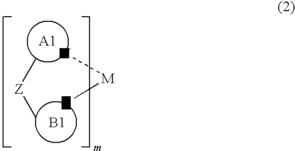
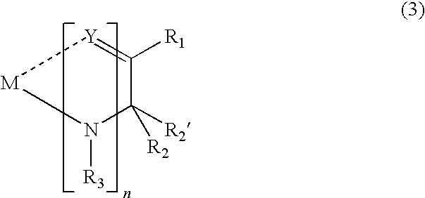
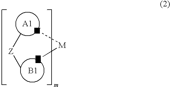
The present invention provides a novel metal complex compound represented by the following general formula (1), and an organic electroluminescence element which has a high efficiency of light emission and a long lifetime, wherein one of organic thin film layers including at least a light emitting layer between an anode and a cathode, at least one of the organic thin film layers contains the metal complex compounds.(L1)mM(L2)n  (1)wherein M represents Ir, Pt and Rh; L1 and L2 represents mutually different bidentate ligands; (L1)mM as a partial structure is represented by general formula (2) and M(L2)n as a partial structure is represented by general formula (3): and m and n are each an integer of 1 or 2, provided that m+n is a integer of 2 or 3.wherein ring A1 represents an aromatic hetrocyclic ring group; and ring B1 represents an aryl group, provided that the ring A1 and the ring B1 are covalently linked to each other via Z which represents a single bond or the like.wherein R1, R2, R2′ and R3 each independently represent an alkyl group or the like; R1 and R2, R1 and R2′, R2 and R2′, R2 and R3, and R2′ and R3 may combine with each other to form a cyclic structure; and Y represents a group represented by O or S.

Description

TECHNICAL FIELD[0001]The present invention relates to a metal complex compound and an organic electroluminescence device using the same, in particular, to an organic electroluminescence device having a high efficiency of light emission and a long lifetime, and a novel metal complex compound for producing the electroluminescence device.BACKGROUND ART[0002]An organic electroluminescence (“electroluminescence” will be occasionally referred to as “EL”, hereinafter) device is a spontaneous light emitting device which utilizes the principle that a fluorescent substance emits light by energy of recombination of holes injected from an anode and electrons injected from a cathode when an electric field is applied. Since an organic EL device of the laminate type driven under a low electric voltage was reported by C. W. Tang et al. of Eastman Kodak Company (C. W. Tang and S. A. Vanslyke, Applied Physics Letters, Volume 51, Pages 913, 1987), many studies have been conducted on organic EL devices...

Claims


Application Information

Patent Timeline
Patent Type & Authority Patents(United States)
IPC IPC(8): H01L51/54C07F15/00C07D213/02C07D231/00
CPCC07D251/24H05B33/14C07D401/14C07D403/10C07D403/14C07D409/14C07D471/04C07D519/00C07F15/0033C07F15/0086C09K11/06H01L51/0067H01L51/0068H01L51/0072H01L51/0085C07D401/10C09K2211/1029C09K2211/1044C09K2211/185H01L51/0059H01L51/0071H01L51/0081H01L51/0087H01L51/5012H10K85/655H10K85/631H10K85/654H10K85/657H10K85/324H10K85/346H10K85/342H10K85/6572H10K50/11C07F17/00C07F17/02C07F15/00
Inventor SAITOU, MASATOSHIIKEDA, HIDETSUGU
Owner IDEMITSU KOSAN CO LTD
Why Eureka
Try Eureka