Microwave plasma exciters

a plasma exciter and microwave technology, applied in the field of atmospheric microwave plasma sources, can solve the problems of inability to pre-programme the adjustment of the process for each process acceptance test, the response time of such systems is often too long for extremely rapid impedance variations imposed

Inactive Publication Date: 2010-09-21
LAIR LIQUIDE SA POUR LETUDE & LEXPLOITATION DES PROCEDES GEORGES CLAUDE
View PDF20 Cites 22 Cited by
  • Summary
  • Abstract
  • Description
  • Claims
  • Application Information

AI Technical Summary

Benefits of technology

[0040]The microwave concentration means, or the impedance transformation means, constitute a distributed capacitive load having the effect of reducing the phase velocity and hence decreasing the characteristic impedance of the waveguide, thereby increasing its frequency bandwidth.
[0045]An example of an inventive device comprises a rectangular section waveguide, having a ridge. The cross section of such a waveguide comprises an appendage or an edge (rectangular or parallelepipedal), which may be continuous, extending from a large side face of the waveguide. According to an alternative, a waveguide with two symmetrical or asymmetrical ridges can be used, extending from the opposite faces of the waveguide, with the same physical effects.

Problems solved by technology

However, in concrete terms, their adjustment cannot be preprogrammed for each process acceptance test, because the latter are formed randomly and their characteristics are generally not transmitted across the inspection interface between the manufacturing equipment and the pollution-stripping system.
This would nevertheless add size, complexity and cost which would all be unacceptable to the device.
Furthermore, the response time of such systems would often be too long for extremely rapid impedance variations imposed by the application.
However, the range of conditions of use of the UPAS is steadily being extended as the processes become more complex with progress in microelectronic circuit miniaturization.
Furthermore, in certain cases, the practical conditions of use generate particularly severe transients which may make the system depart from the range in which the plasma can exist (coupling of a sufficient power to sustain it), causing the system to shut down.
In general, it is found that the optimization parameters inherent in the thinned waveguide concept do not suffice to devise an acceptable impedance matching solution for a complete system designed to form the central active element of a CVD offgas pollution-stripping device.
The problem therefore arises of having plasma sources whereof the impedance matching is fairly insensitive to the variations in the plasma sustaining conditions imposed by its industrial use.

Method used


Image

  • Microwave plasma exciters
  • Microwave plasma exciters
  • Microwave plasma exciters

Examples


Embodiment Construction

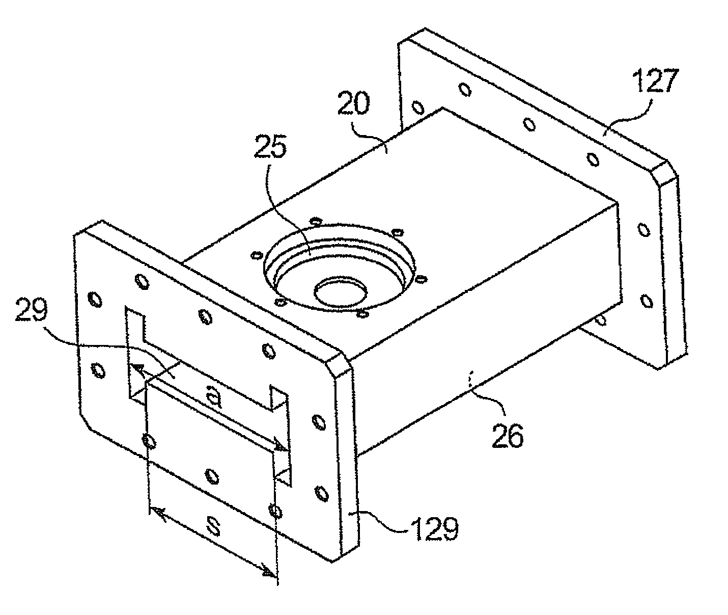
[0036]The invention relates to a microwave plasma generation device, comprising:

[0037]a waveguide, in which means are placed for concentrating the microwaves,

[0038]means for generating a plasma, when the microwave power is coupled with these means, placed in a microwave concentration zone.

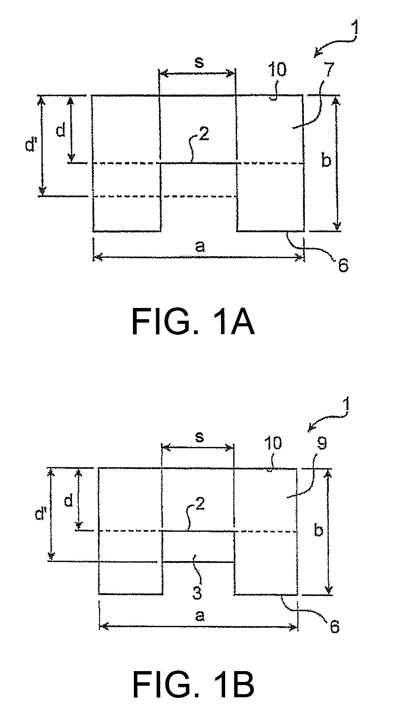
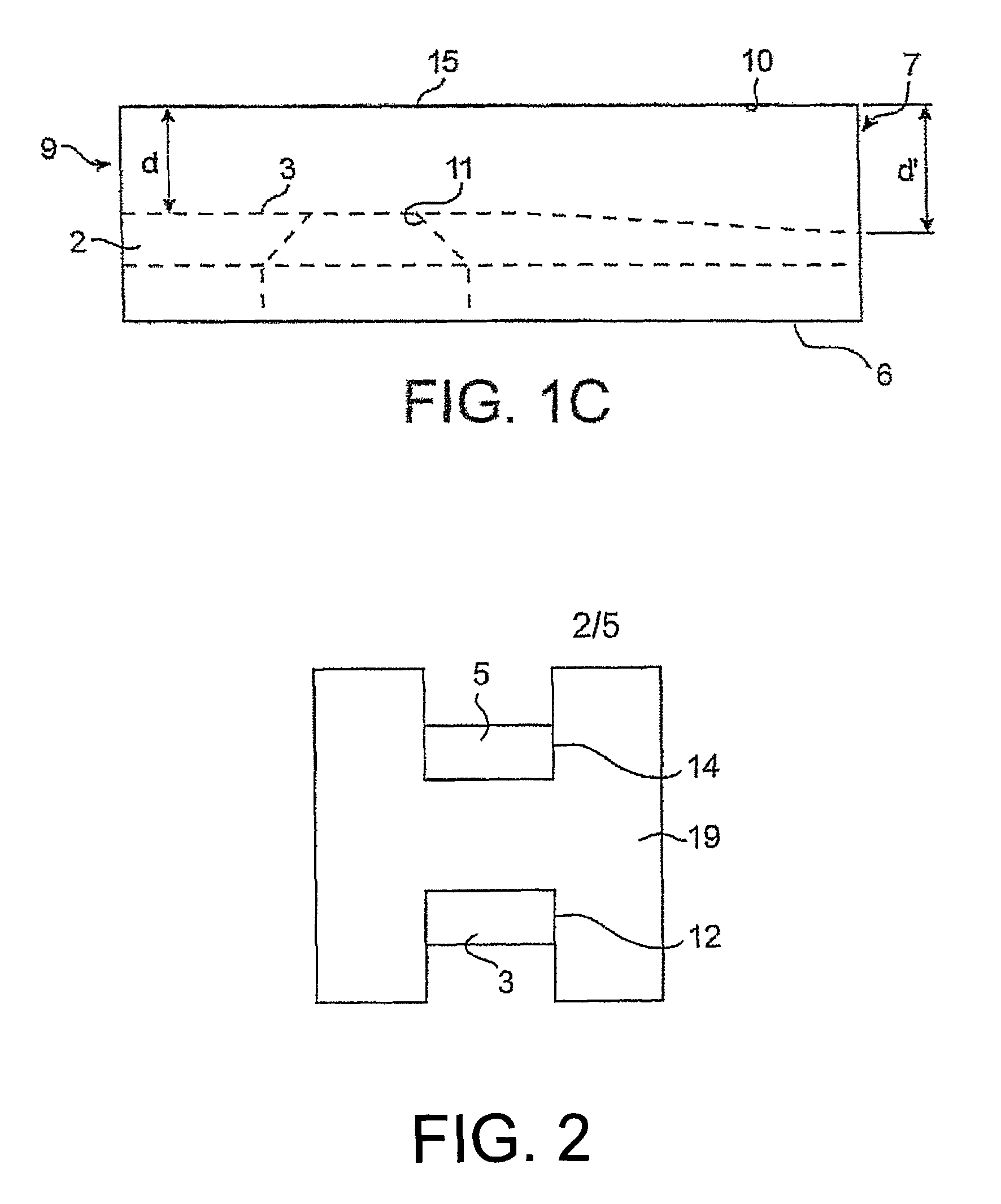
[0039]The microwave concentration means may comprise impedance transformation means between a first side, called the generator side, and a second side, called the short-circuit side.

[0040]The microwave concentration means, or the impedance transformation means, constitute a distributed capacitive load having the effect of reducing the phase velocity and hence decreasing the characteristic impedance of the waveguide, thereby increasing its frequency bandwidth.

[0041]The lowest characteristic impedance serves to obtain an optimal or easier impedance matching than the known devices, particularly since the inventive device has various elements having additional adjustable dimensions (particularly those ...


PUM

PropertyMeasurementUnit
widthaaaaaaaaaa
concentrationaaaaaaaaaa
thicknessaaaaaaaaaa

Abstract

The invention relates to a microwave plasma exciter device which includes a waveguide (23) for concentrating the microwaves; and a plasma generator (110, 120) for forming a plasma, which are disposed in a microwave concentration zone.

Description

TECHNICAL FIELD AND PRIOR ART[0001]The invention relates to the field of atmospheric microwave plasma sources.[0002]In particular, it relates to a method and a microwave plasma device, suitable for strongly and / or rapidly varying operating conditions.[0003]Such conditions are encountered in environments such as gaseous effluents emitted by thin film deposition and etching methods for the production of semiconductors, when a plasma device is used to strip the pollutants from these effluents.[0004]The plasma source serves to couple the microwave power with the discharge to maintain said discharge over long periods, by minimizing the fraction of power reflected to the generator (and hence lost for the application). The power is conveyed from the generator via a power transmission line, for example a hollow rectangular waveguide in one of the standard industrial sections. The transmission line is described physically by a distributed characteristic impedance.[0005]The incident microwave...

Claims


Application Information

Patent Timeline
Patent Type & Authority Patents(United States)
IPC IPC(8): B03C3/016
CPCH05H1/24H05H1/46Y02C20/30H05H1/4622
Inventor ZAKRZEWSKI, ZENONCZYLKOWSKI, DARIUSZJASINSKI, MARIUSZMOISAN, MICHELGUERIN, DANIELLARQUET, CHRISTIANROSTAING, JEAN-CHRISTOPHE
Owner LAIR LIQUIDE SA POUR LETUDE & LEXPLOITATION DES PROCEDES GEORGES CLAUDE
Why Eureka
Try Eureka