
Communication control device and communication control method

a communication control device and communication control technology, applied in the field of wireless lan systems, can solve the problems of packet loss, packet loss, and need for retransmission, and achieve the effect of improving communication quality and system throughput, and efficient use of wireless resources

Inactive Publication Date: 2010-09-28
NTT DOCOMO INC
View PDF6 Cites 6 Cited by
  • Summary
  • Abstract
  • Description
  • Claims
  • Application Information

AI Technical Summary

Benefits of technology

The invention is a communication control device that controls the transmission power of a communication device in an infrastructure mode wireless LAN system using CSMA / CA for access control. The device uses BSS discovery means to determine if there is a neighboring BSS that may affect the communication of the access point or stations. The transmission power setting means sets the transmission power based on the information obtained by measurement of the wireless signal, allowing for optimal transmission power based on the wireless situation. The device also sets different transmission power for each data frame, management frame, and control frame, and mutually communicates with neighboring BSSs to share wireless resources. The device simplifies the determination function of transmission power on the station and reduces interference among BSSs. The invention also allows for faster initialization of transmission power and more rapid control of transmission power. Overall, the invention improves wireless resource utilization and stability of control.

Problems solved by technology

Packet collisions means that, in such a case, the receiving node cannot distinguish arrived packets or perform demodulation of data.
When the receiving node is the destination, it is determined that packet loss occurs, and the need of retransmission arises.
Further, if the packet is management data or control data addressed to a plurality of nodes including the receiving node, degradation of communication quality and reduction in system throughput occur.
If the total received power is equal to or larger than the carrier sense threshold, or if there is an arriving packet which reception is identifiable, when new communication starts, packet collisions occur.
In addition, interference of communication by another node causes congestion of a medium due to packet retransmission.
However, even when Idle, due to the interference of communications being performed remotely, sometimes packets arrive at its own node with received powers such that the total amount of received signal power is equal to or less than the carrier sense threshold, or with received powers that do not allow identification of reception as packets.
Note that the method disclosed in Non-patent Document 1 is particularly effective for a case where a frequency band assigned to the wireless LAN system is not sufficient for traffic, and interference between BSSs cannot be avoided due to the design of the BSS operating frequency.
However, the above-described carrier sense cannot completely avoid packet collisions when a hidden terminal problem arises.
In addition, it is a problem that reduction in throughput due to an exposed terminal problem cannot sufficiently be prevented.
That is to say, a hidden terminal problem occurs when a packet which a sending node “a” sent cannot arrive at another sending node “b”, for example, due to electric wave propagation environment such as obstacles and the distance between sending nodes.
Note that there is a propagation delay time problem as another cause of packet collisions.
The propagation delay time problem means that, in spite of the fact that the carrier sense was performed properly, the sending node “b” cannot detect the start of packet sending from the sending node “a” because of the electric wave propagation delay between sending nodes, and starts sending out the packet almost simultaneously with the sending node “a”.
Meanwhile, the exposed terminal problem is a problem that data is sent and received because of an unnecessary carrier sense, resulting in the reduction in system throughput.
In such a situation, the carrier sense is unnecessary, reducing the system throughput.
However, when the sending node “a” and the receiving node “a” are far from each other, even if the packets are arriving at the receiving node “a”, sometimes the situation of the medium is not verified with the carrier sense of another sending node “b” due to shielding objects in the surrounding and attenuation of packets.
In such a case, when the node “b” sends a packet to the receiving node “b”, packet collisions occur in the receiving node “b” due to the hidden terminal problem.
In addition, in the technique described in Non-patent Document 1, only the transmission power of an AP is controlled, but transmission power of an STA is not controlled.
In addition, the technique described in Non-patent Document 1 assumes the Direct-sequence Spread Spectrum (DSSS) scheme in the physical layer, and is not applicable to the IEEE 801.11a and IEEE 802.11g standards which use the Orthogonal Frequency Division Multiplexing (OFDM) scheme.
The fact that the standard using such a scheme cannot be applied reduces the flexibility of the design of a wireless LAN system.
However, the techniques described in Non-patent Document 2 and Non-patent Document 3 do not consider the effect of interference, which occurs when a plurality of BSSs use the same frequency for communication.

Method used


Image

  • Communication control device and communication control method
  • Communication control device and communication control method
  • Communication control device and communication control method

Examples


Embodiment Construction

[0082]An embodiment of the present invention will be described below.

[0083]Note that in light of the following points, the present embodiment is constituted in order to achieve node transmission power control suitable for a wireless LAN system.

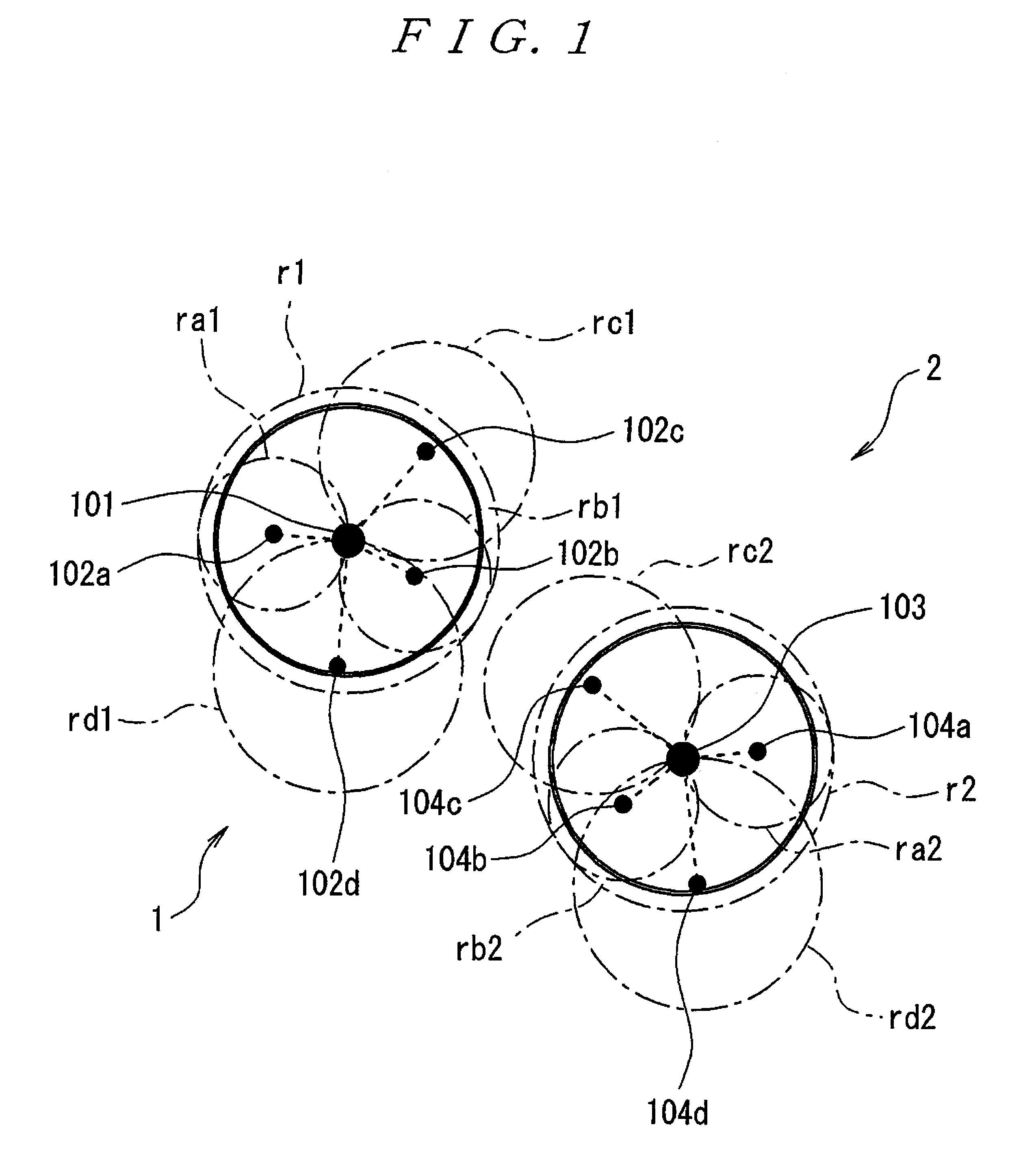
[0084]That is to day, in an IEEE 802.11 standard-compliant wireless LAN system, an infrastructure mode in which a wireless network is comprised of two types of nodes: a base station (AP: access point) and a mobile terminal (STA: station), and an ad hoc mode in which the wireless network is comprised of the stations are defined. In the infrastructure mode, a set of one access point and a plurality of stations attributed to the access point is called a Basic Service Set (BSS), which corresponds to a cell of a cellular system.

[0085]In the present embodiment, an example where a communication device of the present embodiment is applied to the infrastructure mode will be described below.

[0086]In the BSS, transmission from the station to the access p...


PUM


Abstract

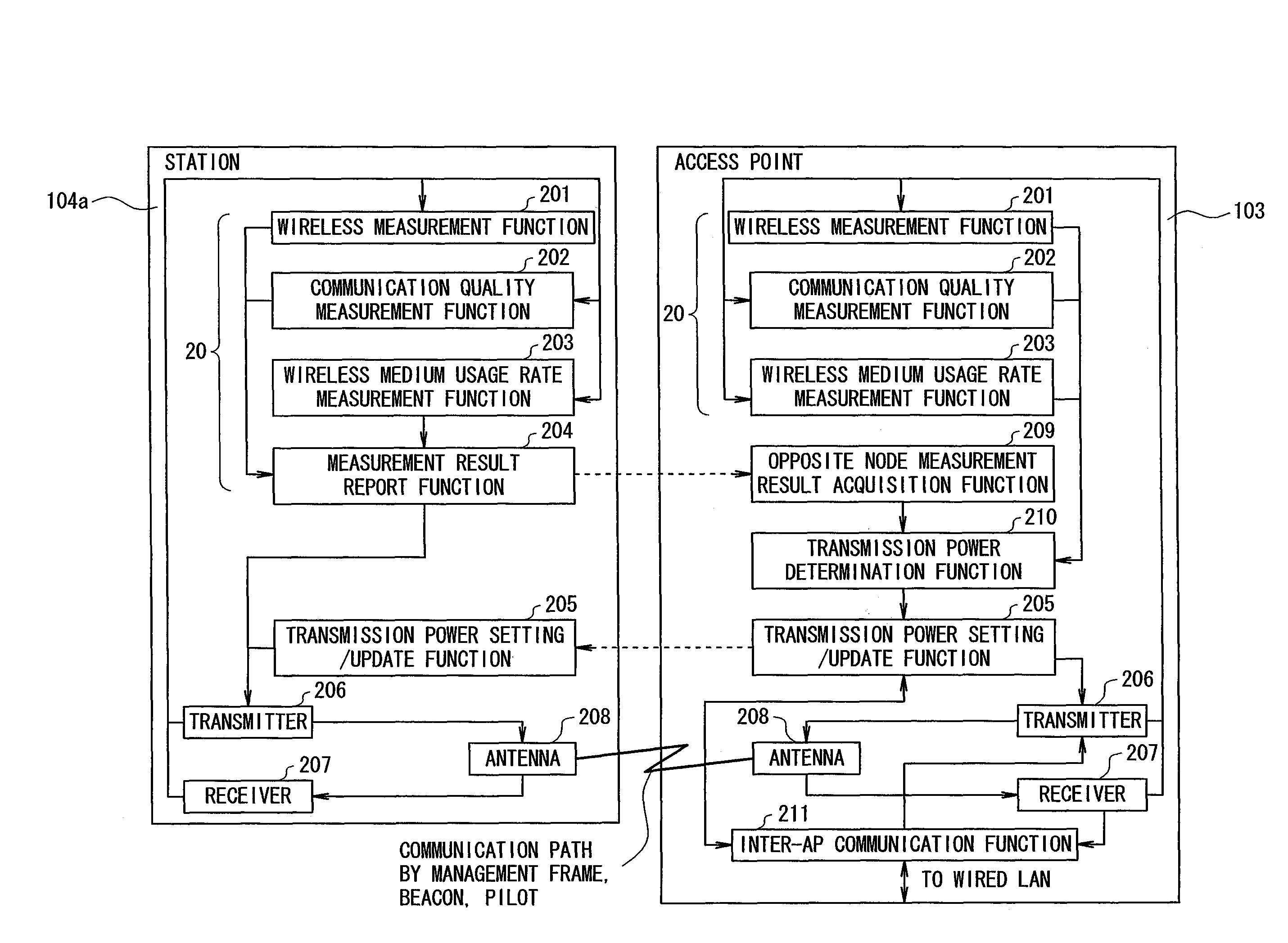
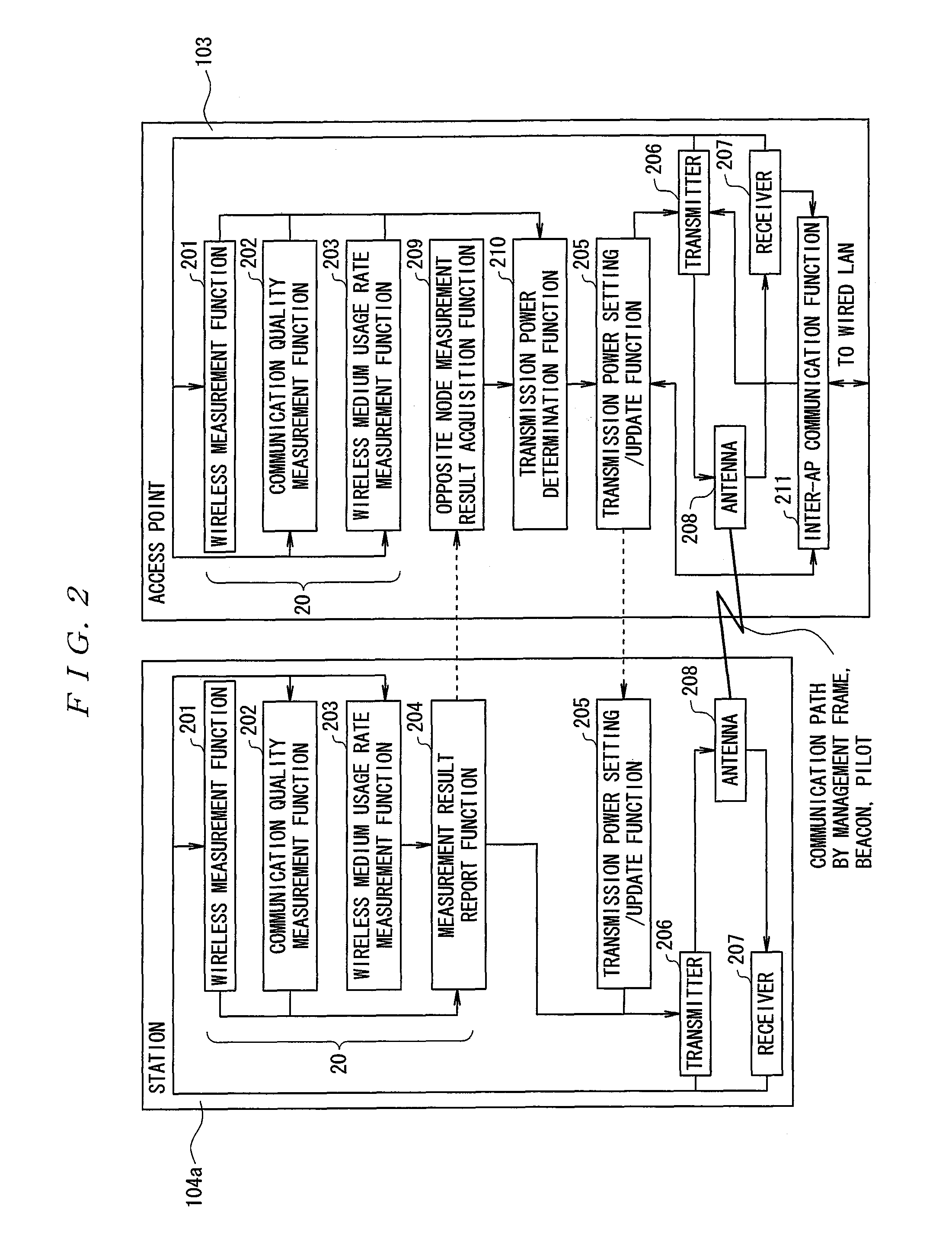
A communication control device is provided which efficiently utilizes wireless resources to improve communication quality and system throughput by appropriately setting and performing node transmission power. The communication control device in a wireless LAN system includes a sender 206, a receiver 207, and an inter-AP communication function 211 for determining, based on at least one of wireless information obtained by measurement of a wireless signal by an access point 103 or a station 104a, or reported wireless information, whether or not there is a neighboring BSS, and a transmission power determination function 210 and a transmission power setting / update function 205 for setting and updating the transmission power of the access point 103 and the station 104a in its own BSS when there is a neighboring BSS in which all the access point have the control function of the transmission power, on the other hand, for maximizing the transmission power when there is no neighboring BSS or when there is a neighboring BSS that does not control the transmission power.

Description

BACKGROUND OF THE INVENTION[0001]1. Field of the Invention[0002]The present invention relates to a wireless LAN system, and more particularly, a communication control device and a communication control method that use an IEEE 802.11 standard-compliant system and the infrastructure mode of the system.[0003]2. Description of the Related Art[0004]In these days, in a wireless local area network (LAN) system, an IEEE 802.11 standard-compliant system is used. In the IEEE 802.11 standard-compliant system, Carrier Sense Multiple Access with Collision Avoidance (CSMA / CA) is used for the access control of a medium (wireless channel).[0005]With CSMA / CA, a node that sends a packet verifies the situation of a medium in order to prevent the loss of transmission data due to packet collisions. That is to say, in a wireless LAN system, before a packet that was sent from a sending node arrives at one receiving node, another packet that was subsequently sent from another sending node sometimes arrives...

Claims


Application Information

Patent Timeline
Patent Type & Authority Patents(United States)
IPC IPC(8): H04B7/185H04B17/00
CPCH04W52/04H04W52/244H04W52/286H04W52/343H04W52/386H04W8/005H04W24/00H04W52/143H04W52/16H04W52/243H04W52/245H04W52/367H04W52/50H04W74/08H04W84/12H04W88/08
Inventor MORI, SHINICHIOOYA, TOMOYUKISUGIYAMA, TAKATOSHI
Owner NTT DOCOMO INC
Learn More