

Total internal reflection holographic microscope
a holographic microscope and internal reflection technology, applied in the field of holographic microscopes, can solve the problems of inability to achieve real space imaging through prisms at a large inclination, inability to achieve real space imaging through digital holography, inability to achieve real space imaging through conventional optical systems, etc., and achieve the effect of rapid acquisition of images
- Summary
- Abstract
- Description
- Claims
- Application Information
AI Technical Summary
Benefits of technology
Problems solved by technology
Method used
Image

Examples
example 1
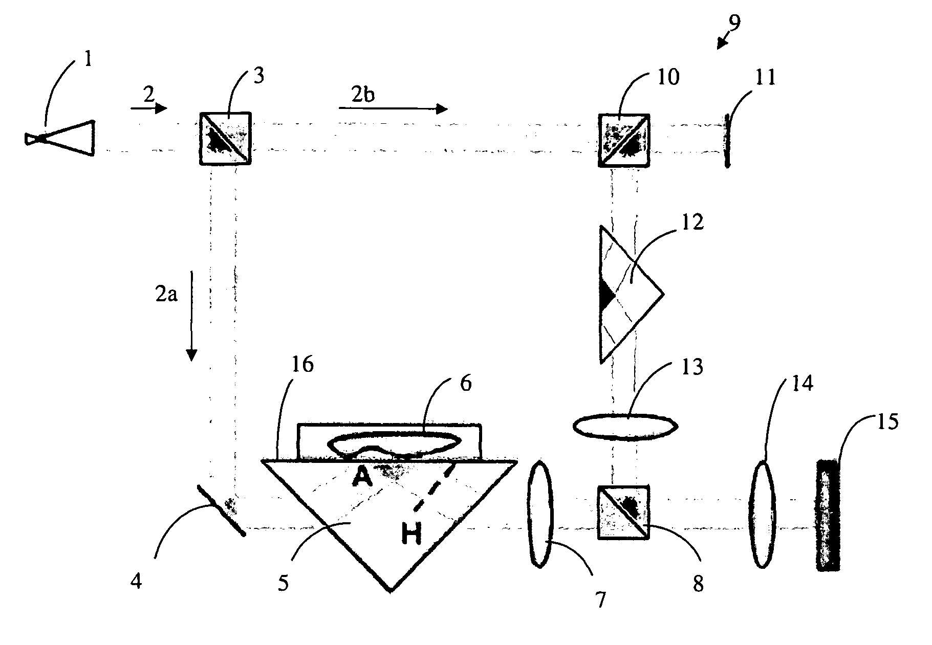
[0075]A holographic interferometer was constructed incorporating a TIR sample mount and microscopic imaging optics. FIG. 7 shows one embodiment of the interferometer for digital holographic microscopy of total internal reflection (TIRHM). A laser input beam (yellow HeNe; λ=594 nm) 2 is emitted from beam emitter 1 and split into two parts, objective beam 2a and reference beam 2b, by beam splitter 3. The objective beam travels to objective reflector 4, where the beam undergoes reflection and is directed toward objective prism 5. The objective beam strikes one face of the prism and undergoes refraction toward the hypotenuse of the prism. Upon striking hypotenuse boundary 16 of objective prism 5, the beam undergoes total internal reflection. To analyze an object, object specimen 6 is placed on the hypotenuse of objective prism 5, causing the objective beam to undergo frustrated total internal reflection. The reflected objective beam travels through the objective prism and exits the pris...
example 2
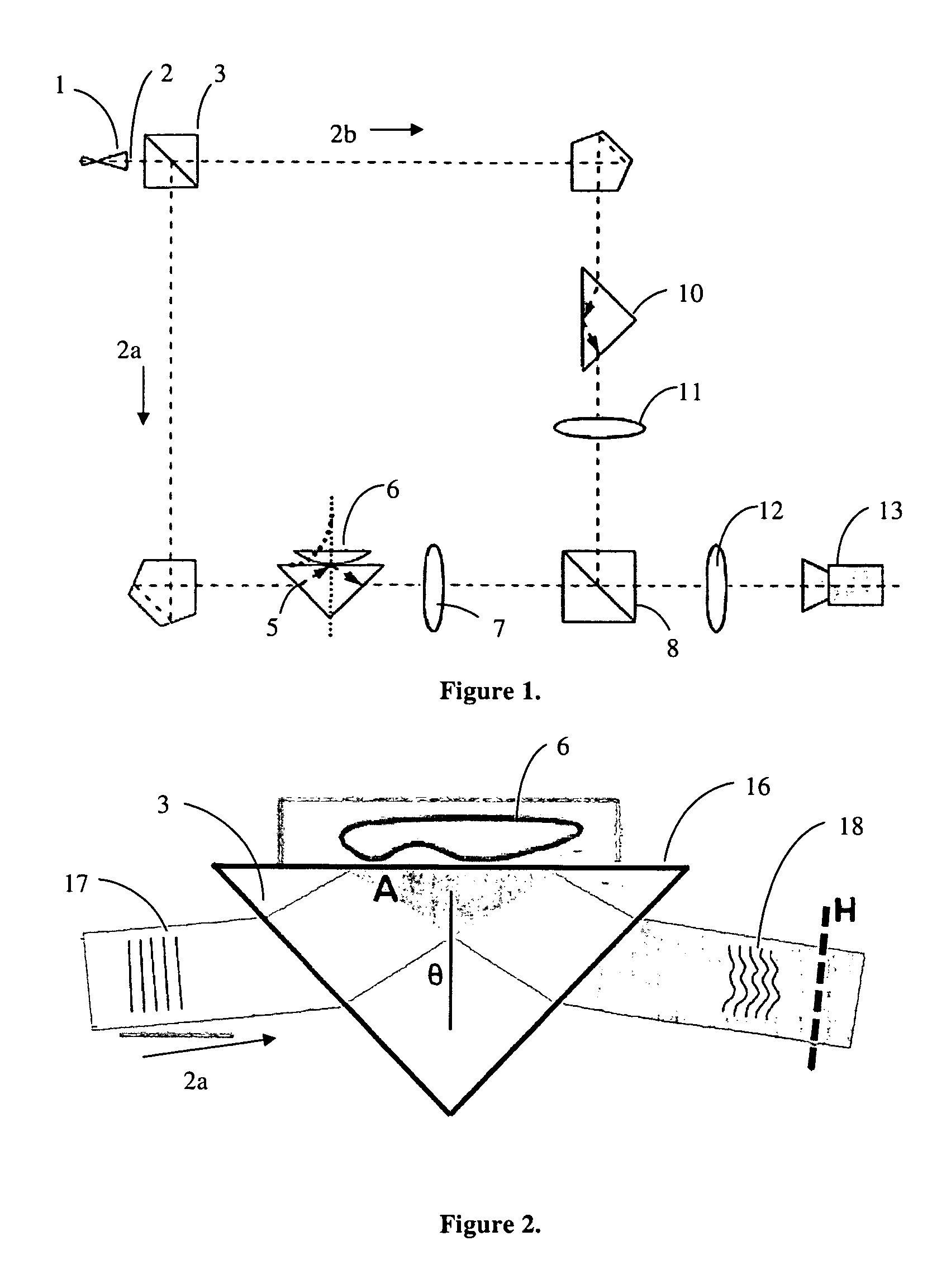
[0078]Objective beam 2a, consisting of an unaltered phase indicated by unaltered phase marker 17, enters objective prism 5 and undergoes total internal reflection at the hypotenuse 16 of the prism, as seen in FIGS. 2 and 8. The presence of the cellular surface near the interface results in frustrated TIR which modulates the phase front of the reflected light, indicated by altered phase marker 16, seen in FIGS. 2 and 8. The fTIR occurring at object plane A modulates the phase front of a plane wave, which propagates (diffracts) to hologram plane H. The imaging system is focused on hologram plane H and image recorder 15 captures the resulting holographic interference pattern. Numerical reconstruction starts from this recorded pattern at hologram plane H and is numerically propagated back to object plane A, which is at an inclination angle β, in order to calculate the phase profile at object plane A, as seen in FIG. 8. This numerically calculated phase profile at object plane A reflects...
example 3
[0079]FIG. 9 shows the preferred configuration of the interferometer for digital holographic microscopy of total internal reflection (TIRHM). Beam emitter 1 is a HeNe yellow laser (λ=594 nm). The emitted beam 2 is expanded by beam expander 19 and strikes beam splitter 3 and is split into objective beam 2a and reference beam 2b. The object beam travels to objective reflector 4, which is a series of two mirrors disposed at 45 degree angles to the incoming objective beam 2a, and is directed toward objective prism 5. To analyze an object, object specimen 6 is placed in sample holder 20 and moved onto the hypotenuse of objective prism 5, causing the objective beam to undergo frustrated total internal reflection. The reflected objective beam travels through the objective prism and exits the prism opposite the entering objective beam. Objective beam 2a travels through the 40 mm objective lens 7, whereby the beam is magnified. The magnified objective beam then travels to beam splitter 8.
[00...
PUM
 Abstract
Description
Claims
Application Information