Eureka AIR delivers breakthrough ideas for toughest innovation challenges, trusted by R&D personnel around the world.

Method and apparatus for multi-antenna signal transmission in RF long-distance wireless BS

a multi-antenna signal and wireless bs technology, applied in the field of base transceiver station technology, can solve the problems of nonlinear distortion of wireless signal transmission between the rrus and the main bts, difficult to solve the coverage problem of wireless network with conventional bts technology, and introduce nonlinear distortion. the effect of network cost reduction

Inactive Publication Date: 2010-10-19
UTSTARCOM TELECOM CO LTD +1
View PDF7 Cites 38 Cited by
  • Summary
  • Abstract
  • Description
  • Claims
  • Application Information

AI Technical Summary

Benefits of technology

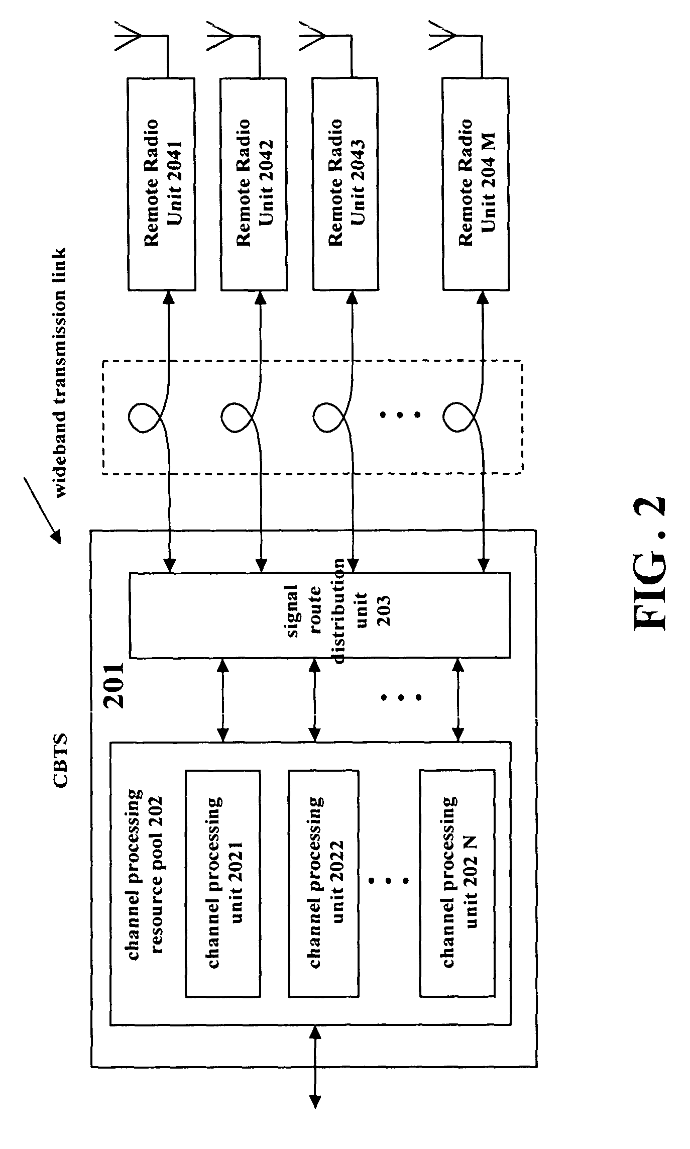
[0022]To solve the problems present in the wireless signal transmission between the RRU and the main BTS in the existing technology, it is therefore an object of the present invention to provide a method and corresponding system for transmitting a plurality of antenna signals in wireless BTS using RRH technology, which is based on the method and system of signal transmission in Base Transceiver Station based on remote radio head. The effective wireless signal transmission between the RRU and the main BTS can be realized without specific transmission network, and therefore networking cost can be reduced, using the existing bandwidth resource in the existing telecommunication transmission network, especially accessing directly the transmission technology based on SDH / OTN in the existing technology between the RRU and the main BTS, that is, adopting STM-N / OTM-n standard interface directly.
[0023]More particularly, another object of the present invention is to provide a method and corresponding system for transmitting a plurality of antenna signals in wireless BTS using RRH technology, under the circumstance of using a plurality of antennas for transmitting, so as to ensure strict time / phase relations between various antenna signals, and enable the transmission delays to the CBTS for various antenna signals to be the same. Typically, according to the method and corresponding system for transmitting a plurality of antenna signals in wireless BTS using RRH technology proposed in the invention, the complexity of the system can be simplified when performing time delay measurement and time delay compensation on the transmission links corresponding to various antennas, so as to ensure strict time / phase relations between various antenna signals under the circumstance of using a plurality of antennas for transmitting.

Problems solved by technology

In mobile communication systems, there are wireless network coverage problems that are more difficult to be solved with conventional BTS technologies, such as, indoor coverage of high-rise buildings, coverage hole, or the coverage of shadow zone.
In the two BTS systems using RRH technology discussed above, the key problem to be solved is the wireless signal transmission between the RRUs and the main BTS.
Typically, analog intermediate frequency or analog radio frequency signal transmission scheme is adopted, although it is easier to adopt analog signal transmission scheme, there will introduce disturbing components, for example noise, etc, in analog lines, and the signal modulation in the transmission will also introduce nonlinear distortion.
In addition, the analog transmission may decrease the utilization of transmission line, and hamper the implementation of large capacity multiplex technology; therefore, it is difficult to adopt the analog transmission scheme in large scale networking.
On the other hand, SDH (Synchronous Digital Hierarchy) and OTN (Optical Transmission Network) based on such Wavelength Division Multiplex technology as DWDM (Dense Wavelength Division Multiplex) / CWDM (Coarse Wavelength Division Multiplexing) have been widely used in backbone network and wideband Metropolitan Area Network (MAN), but the existing technology of digital transmission between the RRU and the main BTS uses specific transport protocols and specification, and therefore, it is difficult to use the existing maturate wideband transmission resources in the existing telecommunication network, so the networking cost is increased.
Moreover, there are problems, such as nonflexible networking and complicated maintenance and management, in the existing technology of digital transmission between the RRU and the main BTS.
Time delay compensation technology, as the method adopted in CPRI technology specification, requires measuring precisely the time delays of transmission links corresponding to various antennas, and it is only adapted to the networking with fixed time delay, such as point to point link, etc. . . . When intermediate transmission network node is present, the time delay will vary at random because of the vary of network traffic, so time delay measurement and time delay compensation should be performed on the transmission links corresponding to various antennas continuously, in doing so, the system is complicated, and strict time / phase relations between various antenna signals required by the multi-antenna technology are usually hard to be realized.

Method used


Image

  • Method and apparatus for multi-antenna signal transmission in RF long-distance wireless BS
  • Method and apparatus for multi-antenna signal transmission in RF long-distance wireless BS
  • Method and apparatus for multi-antenna signal transmission in RF long-distance wireless BS

Examples


first embodiment

The First Embodiment

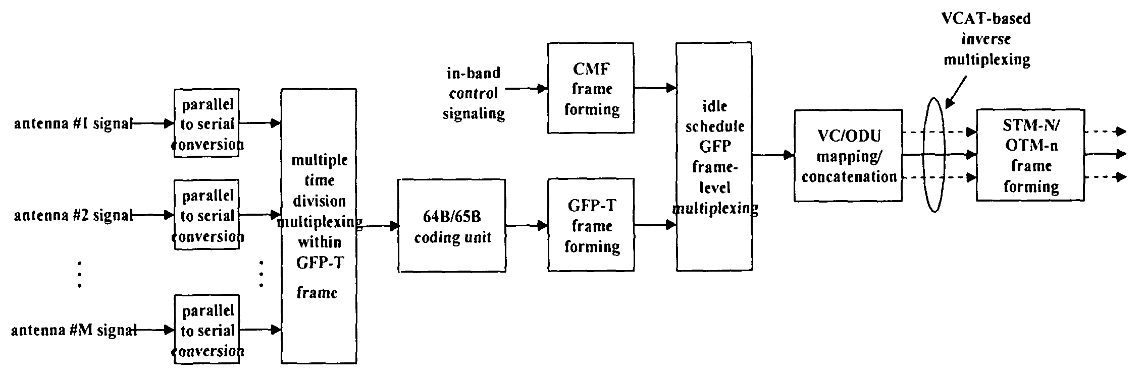
[0056]FIGS. 6A, 6B schematically show the SDH / OTN-based transmission between the main BTS and the Remote Radio Unit(s) in accordance with the first embodiment of time division multiplexing a plurality of antenna signals of the present invention.

[0057]As shown in FIG. 6A, firstly at the transmit end, parallel to serial conversion is performed on the antenna signals of various antenna branches, such as antenna #1 signal, antenna #2 signal, . . . antenna #M signal, and the converted signals are multiplexed to one signal stream (digital wireless signal data stream) within one GFP-T frame using isochronous slot time division multiplex technology.

[0058]Then the digital wireless signal data stream obtained after multiple time division multiplex within the GFP-T frame and an in-band control signaling are transmitted together. Typically, as shown in FIG. 6A, using CMF frame to transmit the in-band control signaling, the in-band control signaling is sent in the manner of a...

second embodiment

The Second Embodiment

[0061]FIGS. 7A, 7B schematically show the SDH / OTN-based transmission between the main BTS and the Remote Radio Unit(s) in accordance with the second embodiment of time division multiplexing a plurality of antenna signals of the present invention.

[0062]As shown in FIG. 7A, firstly at the transmit end, parallel to serial conversion is performed on the antenna signals of various antenna branches, such as antenna #1 signal, antenna #2 signal, . . . antenna #M signal, and the converted signals are multiplexed to one signal stream (digital wireless signal data stream) within one GFP-T frame using isochronous slot time division multiplex technology;

[0063]Then the digital wireless signal data stream obtained after multiple time division multiplex within one GFP-T frame and an in-band control signaling are transmitted together. Typically, as shown in FIG. 7A, the in-band control signaling is transmitted using 64B / 65B code block control character bit. At the transmit end,...

third embodiment

The Third Embodiment

[0065]FIGS. 8A, 8B schematically show the SDH / OTN-based transmission between the main BTS and the Remote Radio Unit(s) in accordance with the third embodiment of time division multiplexing a plurality of antenna signals of the present invention.

[0066]As shown in FIG. 8A, firstly at the transmit end, parallel to serial conversion is performed on the antenna signals of various antenna branches, such as antenna #1 signal, antenna #2 signal, . . . antenna #M signal, and the converted signals and an in-band control signaling are multiplexed to one signal stream (digital wireless signal data stream) within one GFP-T frame using isochronous slot time division multiplex technology.

[0067]Then the digital wireless signal data stream multiplexed is mapped to a 64B / 65B code block by a 64B / 65B coding unit to form a GFP-T client data frame, and then the GFP-T frame is mapped to a STM-N / OTM-n frame based on the existing technology to realize the transmission based on SDH / OTN. S...


PUM


Abstract

The invention relates to a method for transmitting a plurality of antenna signals in a wireless Base Transceiver Station (BTS) using Remote Radio Head (RRH) technology and the corresponding system. The method includes the steps of: transmitting signals over the transmit channel using Synchronous Digital Hierarchy (SDH) / Optical Transmission Network (OTN), multiplexing the plurality of antenna signals adopting the manners of time division multiplex or GFP frame-level multiplex; forming the multiplexed antenna signal stream and in-band control signaling stream into Generic Framing Procedure (GFP) frame; or forming the plurality of antenna signals and the plurality of respective control signals on the in-band control signaling channel into a plurality of respective GFP frames in parallel; and further mapping the GFP frames to STM-N / OTM-n frames, therefore multiplexing the plurality of antenna signals and the in-band control signaling stream to realize the SDH / OTN-based transmission. According to the invention, in the circumstance of using a plurality of antennas for transmitting signals, the strict time and phase relations between various antenna signals can be ensured, and also system complexity can be simplified, the transmission delays from various antenna signals to CBTS are totally the same.

Description

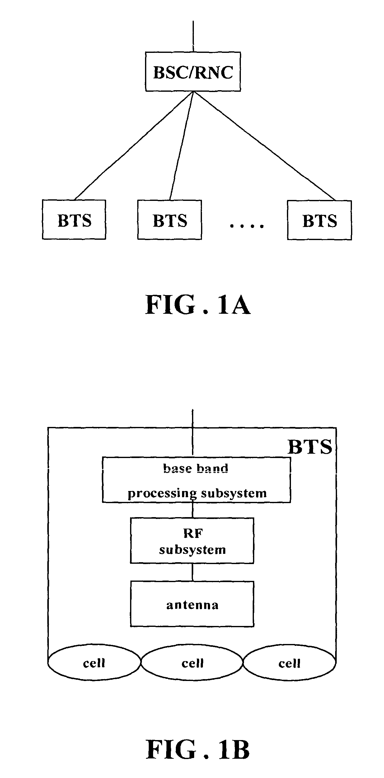
FIELD OF THE INVENTION[0001]The present invention relates to a Base Transceiver Station technology used in mobile communication system, and more particularly, to a method and corresponding communication system of signal transmission in the Base Transceiver Station system using remote radio head (RRH) technology and multi-antenna technology, wherein the multi-antenna technology includes such technologies as transmit diversity, receive diversity, Multiple-Input Multiple-Output (MIMO) and Smart Antenna or Antenna Array, etc.BACKGROUND OF THE INVENTION[0002]1. Remote Radio Head technology, Centralized Base Transceiver Station (CBTS) and signal transmission[0003]As illustrated in FIG. 1A, in mobile communication systems, a wireless access network is typically composed of Base Transceiver Stations (BTSs) and Base Station Controllers (BSCs) or Radio Network Controllers (RNCs) for controlling a plurality of BTSs. Wherein the BSC is mainly composed of a base band processing subsystem, a radi...

Claims


Application Information

Patent Timeline
Patent Type & Authority Patents(United States)
IPC IPC(8): H04W4/00H04B7/04H04J3/16H04Q7/28
CPCH04B7/04H04J3/1617H04J2203/0035
Inventor LIU, SHENG
Owner UTSTARCOM TELECOM CO LTD
Why Eureka
Eureka Blog
Learn More