Method for dewatering slurry from construction sites

a technology for construction sites and slurry, applied in sedimentation separation, coastline protection, centrifugal force sediment separation, etc., can solve the problems of inherently problematic construction projects that require installation across streams and other water resources, and bags can often clog very easily, so as to achieve the effect of not significantly reducing the effectiveness of a filtering medium over tim

Active Publication Date: 2010-10-26
DENNY HASTINGS FLP 14
View PDF42 Cites 12 Cited by
  • Summary
  • Abstract
  • Description
  • Claims
  • Application Information

AI Technical Summary

Benefits of technology

[0006]The second product is a new filter skirt material comprising of natural and synthetic fibrous matting impregnated with polymeric compounds that promotes flocculation of suspended soil particles to enhance settling rates and adsorption onto the surface area of the fiber matting and is sold under the brand name FlocMat™. The unique combination of the bag and skirt to form filter zones can result in removing substantially all solids from slurry passing therethrough.
[0008]In another aspect the invention is a treatment system that involves channeling the pump effluent at a construction site through a wide and long pre-fabricated channel. The sides of the pre-fabricated channel are formed using the filter bags filled with recycled (chopped or shredded) rubber and hardwood chip filter media. Shredded rubber, particularly, tends to remain in the ballast as discrete particulate and does not tend to form “clogs” as silt accumulates so that its effectiveness as a filtering medium is not significantly diminished over time.

Problems solved by technology

Construction projects that require installations across streams and other water resources are inherently problematic relative to issues of surface-water quality.
These bags often clog very easily and are marginally successful in solids reduction with little removal of fine, colloidal solids associated with many clay soils.

Method used


Image

  • Method for dewatering slurry from construction sites
  • Method for dewatering slurry from construction sites
  • Method for dewatering slurry from construction sites

Examples


Embodiment Construction

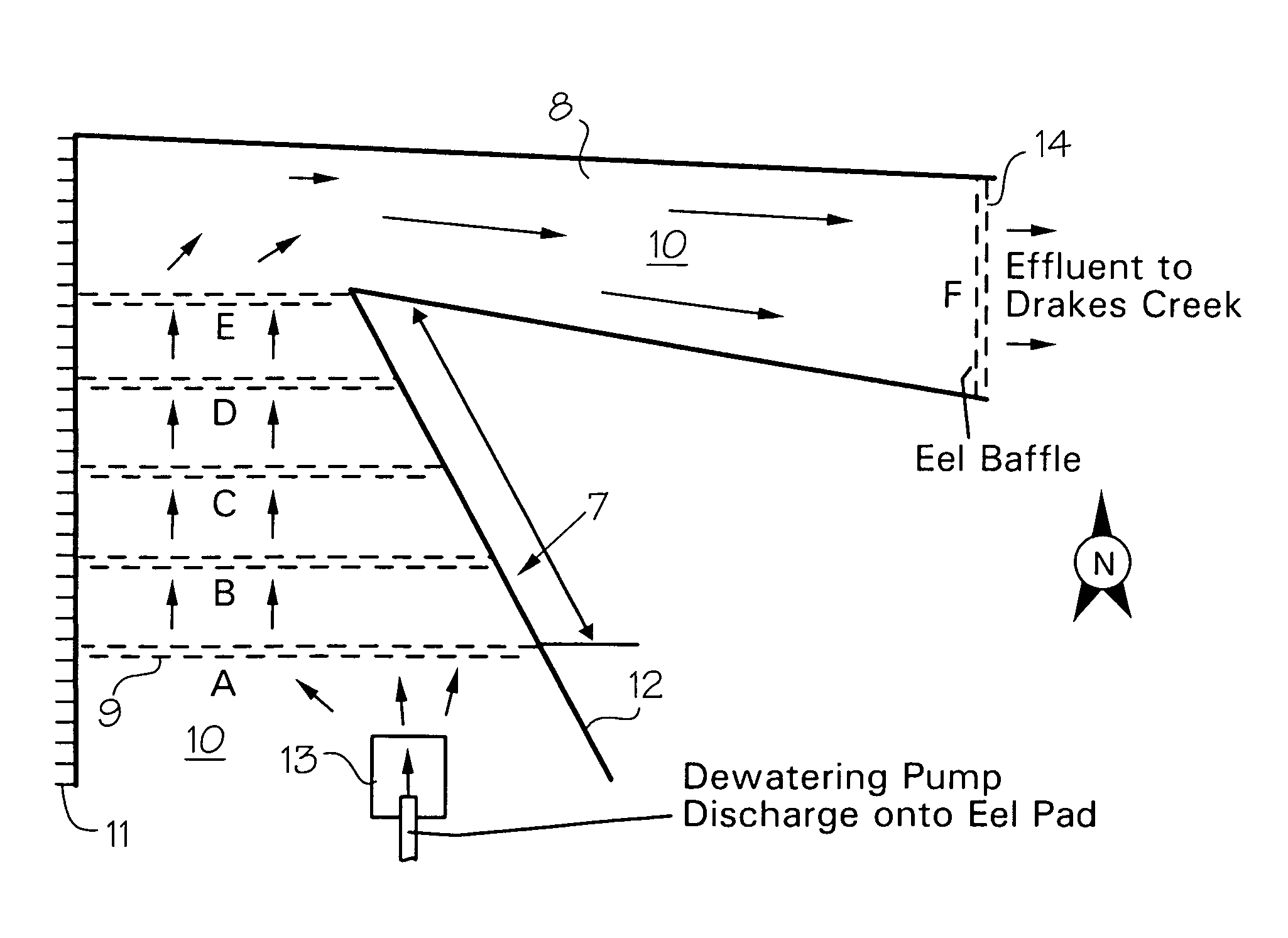
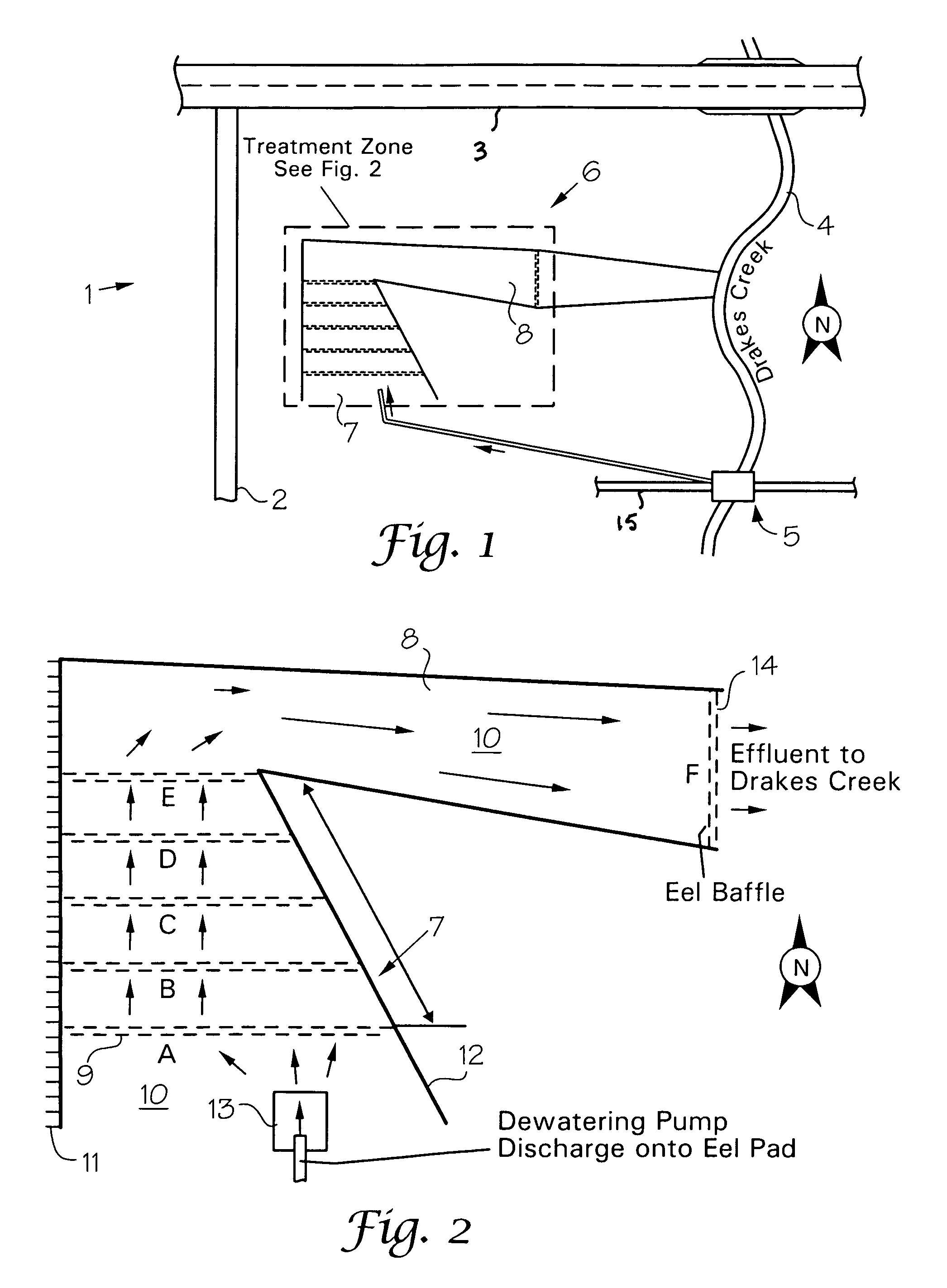
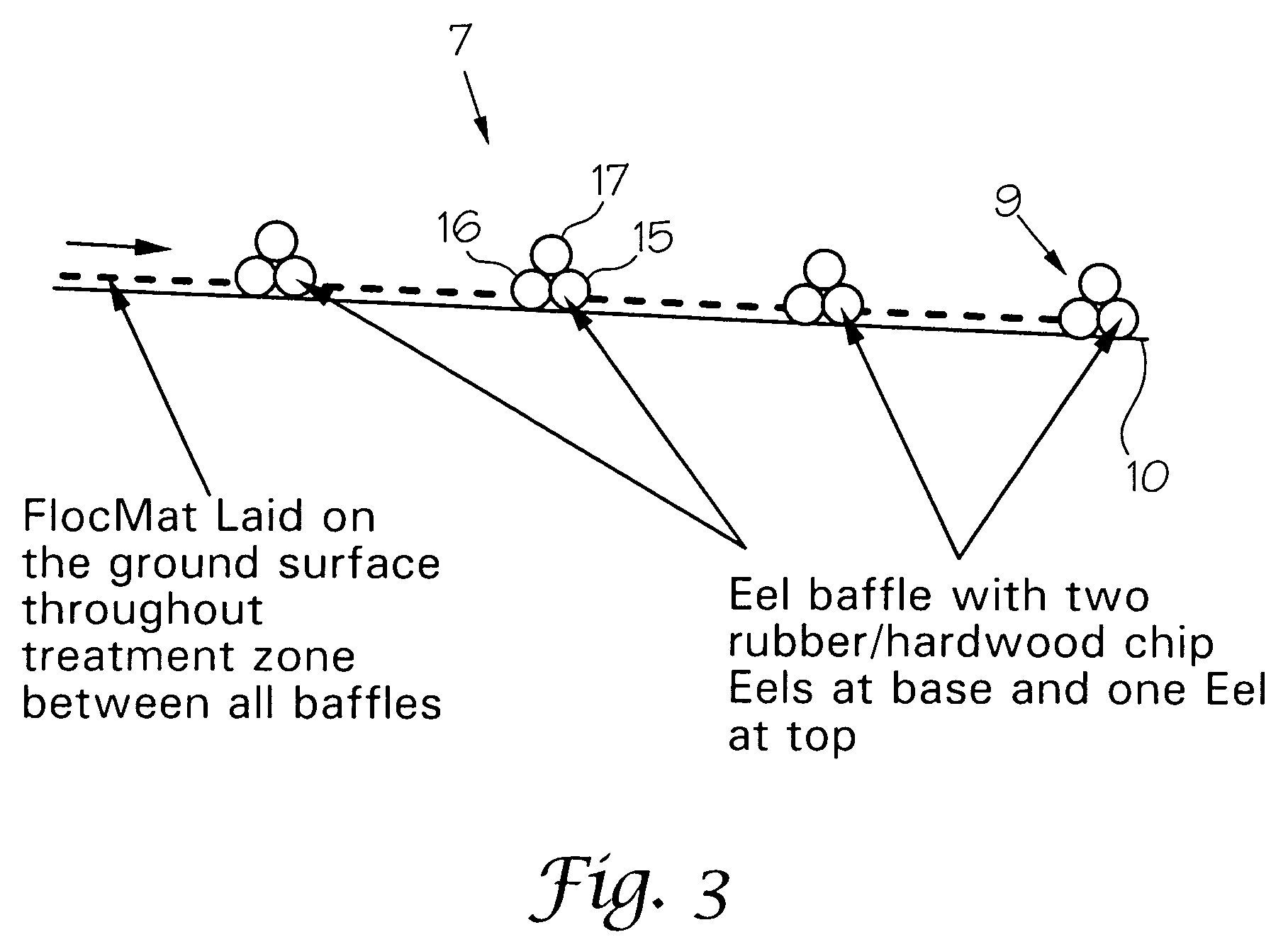
[0014]Looking at FIGS. 1 and 2, construction site 1 is shown bounded by a temporary construction road 2, State Road 3, and creek 4 over which pipeline crossing 5 is being constructed. Water flow is indicated by the arrows in FIG. 2. Treatment zone 6 comprises primary zone 7 and secondary zone 8. Baffles 9(A-E) are arranged in parallel rows in zone 7 between baffle walls 11 and 12. The floor 10 of the primary zone 7 comprises filter skirt 10. The primary zone 7 receives the flow from pump 13 from which the slurry flows through the baffles 9(A-E) as it is being de-watered and then into the second zone 8 through interface or connecting baffle 9E. The treated water exits secondary zone 8, which also has a filter skirt floor 10, through end baffle 14 which serves as a fluid filter dam. Water flow in FIGS. 1 and 2 is indicated by the arrows. The stacking of filter bags 16 to form baffles 9 is shown in cross-section in FIG. 3 which is a cross-section of zone 7.

[0015]The foregoing arrangeme...


PUM

PropertyMeasurementUnit
lengthaaaaaaaaaa
lengthaaaaaaaaaa
diameteraaaaaaaaaa

Abstract

A method of removing solids from the slurry at a construction site located on or near a stream in order to improve the quality of water discharged into the stream by forming treatment zones for receiving slurry, said zones comprising walls of filter bags and floors of filter skirts, said bags and skirts comprising geotextile material and the bags being filled with a shredded rubber and woodchip combination.

Description

CROSS REFERENCE TO RELATED APPLICATION[0001]This application claims priority from Provisional Application Serial No. 61 / 011,075, filed Jan. 14, 2008.FIELD OF THE INVENTION[0002]This invention relates to erosion control and more particularly to controlling the quality of water at construction sites near streams.SUBJECT MATTER INCORPORATED BY REFERENCE[0003]The specification and drawings of U.S. Pat. No. 7,449,105 which issued Nov. 11, 2008 and which is owned by the assignee of this application is incorporated herein by reference.BACKGROUND[0004]Construction projects that require installations across streams and other water resources are inherently problematic relative to issues of surface-water quality. Proper protocols must be followed for handling in-stream construction work to prevent suspended-solids release into the water body. This often involves the temporary isolation of the proposed crossing location by creating temporary dams immediately upstream and downstream of the const...

Claims


Application Information

Patent Timeline
Patent Type & Authority Patents(United States)
IPC IPC(8): B01D36/04C02F11/121
CPCC02F11/121
Inventor HASTINGS, DENNYSEAGROVES, KYLESLIGER, STEPHEN M.
Owner DENNY HASTINGS FLP 14
Why Eureka
Try Eureka