
Dielectric ceramic composition, multi-layer ceramic capacitor and manufacturing method thereof

a technology of ceramic capacitors and dielectric ceramics, applied in the direction of fixed capacitors, basic electric elements, electrical equipment, etc., can solve the problems of insufficient specific resistance, inability to obtain sufficient specific resistance, and inability to meet the requirements of severe circumstances

Active Publication Date: 2010-10-26
TAIYO YUDEN KK
View PDF4 Cites 29 Cited by
  • Summary
  • Abstract
  • Description
  • Claims
  • Application Information

AI Technical Summary

Benefits of technology

[0018]According to the second embodiment, a dielectric ceramic composition having a specific resistance of higher than 1000 MΩm under a high temperature circumstance can be obtained further.
[0020]According to the third embodiment, a multi-layer ceramic capacitor having a temperature characteristic satisfying an X8R property, having a specific resistance of higher than 100 MΩm under a high temperature circumstance and, further, a high temperature accelerated life property in excess of 10,000 sec at 150° C. -25 V / μm can be provided.
[0022]According to the fourth embodiment, a multi-layer ceramic capacitor having a specific resistance of higher than 1000 MΩm under a high temperature circumstance, and a high temperature accelerated life property exceeding 100,000 seconds at 150° C.-25 V / μm can be provided.

Problems solved by technology

However, reliability under severe circumstances has been required in recent years for such multi-layer ceramic capacitors depending on the application use.
However, the dielectric ceramic composition and the multi-layer ceramic capacitor described above involved a problem that a sufficient specific resistance can not always be obtained in a case of further reducing the thickness of dielectric ceramics between internal electrodes for further reducing the size and increasing the capacitance.
Particularly, they involved a problem that the specific resistance is not sufficient under a high temperature circumstance exceeding 125° C.

Method used


Image

  • Dielectric ceramic composition, multi-layer ceramic capacitor and manufacturing method thereof
  • Dielectric ceramic composition, multi-layer ceramic capacitor and manufacturing method thereof

Examples


example

Example 1

[0041]BaTiO3, with an average value for the particle diameters of 0.45 μm, and MgO, Mn2O3 (as MnO3 / 2 conversion), Ho2O3 (as HoO3 / 2 conversion) and SiO2 were provided by weighing them so as to form the composition ratio in Table 1 as the starting materials. The average value for the particle diameters of BaTiO3 is determined by observing particles under SEM (Scanning Electron Microscope), measuring the maximum diameter in a predetermined direction for the number of 300 and taking arithmetic mean of the maximum diameter for the number of particles of 300. The subsequent indication for the average value of particle diameters for BaTiO3 is also identical.

[0042]

TABLE 1BaTiO3MgMReSiAdditiveAdditiveAdditiveAdditiveAdditiveamountamountamountamountamountmolmolElementmolElementmolmolRe / Si*11001.0Mn0.2Ho62.52.4021001.0Mn0.2Ho632.00*31001.0Mn0.2Ho63.51.71*41001.0Mn0.2Ho531.6751001.0Mn0.2Ho732.33*61001.0Mn0.2Ho9.92.53.9671001.0Mn0.2Ho9.933.3081001.0Mn0.2Ho9.93.52.8391001.0Mn0.2Ho832.67*...

example 2

[0048]Starting materials were prepared so as to provide the composition ratios in Table 3, and dielectric ceramic powders were formed in the same manner as in Example 1. In this case, Ho was replaced with other rare earth elements and the effects thereof were verified.

[0049]

TABLE 3BaTiO3MgMReSiAdditiveAdditiveAdditiveAdditiveAdditiveamountamountamountamountamountmolmolElementmolElementmolmolRe / Si211001.0Mn0.2Y8.03.52.29221001.0Mn0.2Sm8.03.52.29231001.0Mn0.2Eu8.03.52.29241001.0Mn0.2Gd8.03.52.29251001.0Mn0.2Tb8.03.52.29261001.0Mn0.2Dy8.03.52.29271001.0Mn0.2Er8.03.52.29281001.0Mn0.2Tm8.03.52.29291001.0Mn0.2Yb8.03.52.29301001.0Mn0.2Ho:Y = 1:18.03.52.29

[0050]Multi-layer ceramic capacitors were formed from the dielectric ceramic powders described above in the same manner as in Example 1, and the permittivity, the temperature characteristic (TC), the specific resistance, and the lifetime property were measured and they are collectively shown in Table 4.

[0051]

TABLE 4SpecificLife timeresista...

example 3

[0053]Starting materials were prepared so as to provide the composition ratios in Table 5 and dielectric ceramic powders were formed in the same manner as in Example 1. In this case, the additive amount of Mg was changed and the effects thereof were verified.

[0054]

TABLE 5BaTiO3MgMReSiAdditiveAdditiveAdditiveAdditiveAdditiveamountamountamountamountamountmolmolElementmolElementmolmolRe / Si*311000.2Mn0.2Ho8.03.52.29321000.4Mn0.2Ho8.03.52.29331001.0Mn0.2Ho8.03.52.29341002.0Mn0.2Ho8.03.52.29351003.0Mn0.2Ho8.03.52.29*361004.0Mn0.2Ho8.03.52.29* Out of the range of an embodiment of the invention

[0055]Multi-layer ceramic capacitors were formed from the dielectric ceramic powders described above in the same manner as in Example 1, and the permittivity, the temperature characteristic (TC), the specific resistance, and the life time property were measured and they are collectively shown in Table 6.

[0056]

TABLE 6SpecificLife timeTCresistancepropertyPermittivity(%)Ωmsec*312550−10.91.1E+098.5E+03322...


PUM

PropertyMeasurementUnit
particle diameteraaaaaaaaaa
temperature accelerated life propertyaaaaaaaaaa
thicknessaaaaaaaaaa

Abstract

A multi-layer ceramic capacitor has a temperature characteristic satisfying an X8R property and has a high specific resistance under a high temperature circumstance, in which the dielectric ceramic composition forming the dielectric ceramics is expressed by a formula: BaTiO3+aMgO +bMOx+cReO3 / 2+dSiO2, wherein MgO represents MgO conversion, MOx represents oxide conversion for 1 atom in 1 molecule of at least one metal selected from V, Cr, and Mn, ReO3 / 2 represents oxide conversion for 1 atom in 1 molecule of at least one rare earth metal selected from Sm, Eu, Gd, Tb, Dy, Ho, Er, Tm, Yb, and Y, and SiO2 represents SiO2 conversion, and wherein 0.4≦a≦3.0 mol, 0.05≦b≦0.4 mol, 6.0≦c≦16.5 mol, 3.0≦d≦5.0 mol, 2.0≦c / d≦3.3, based on 100 mol of BaTiO3.

Description

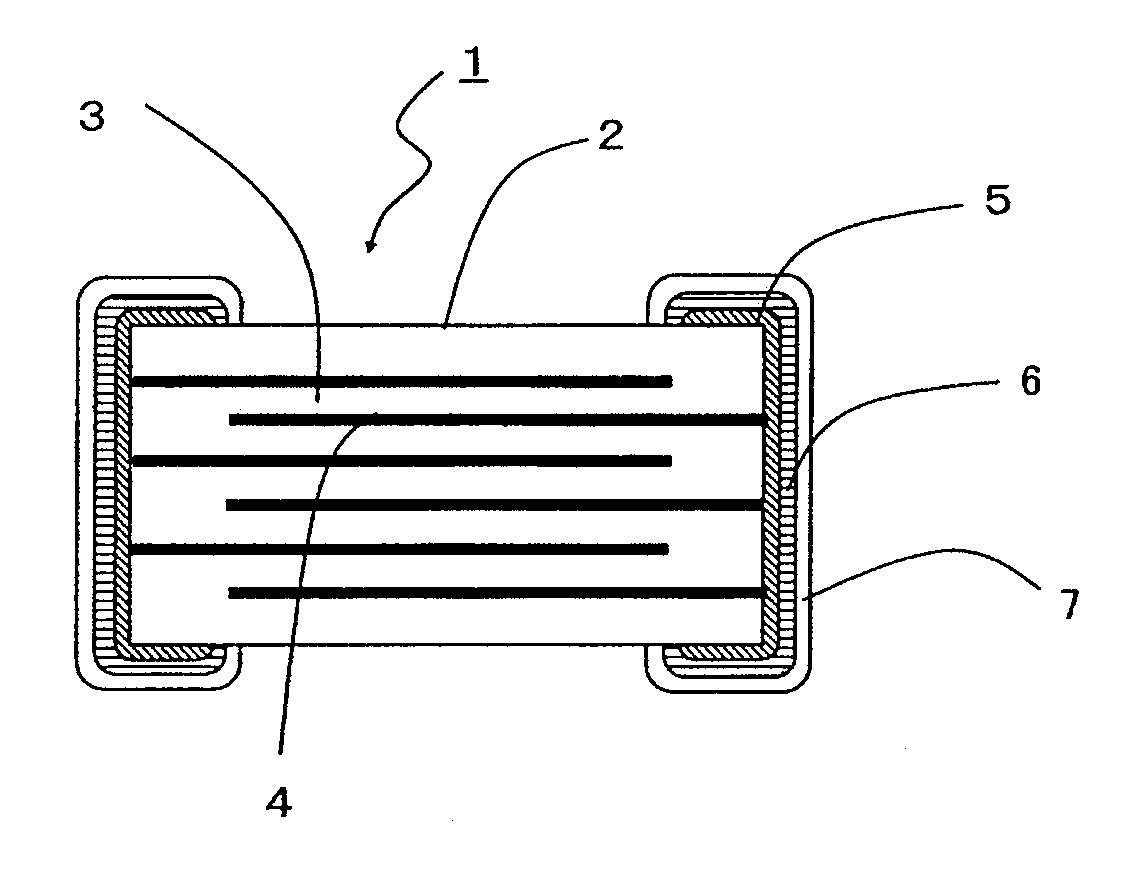
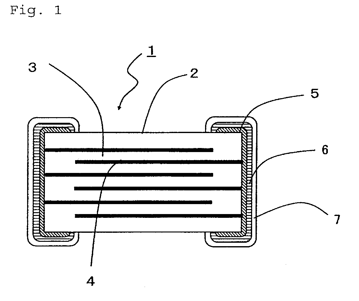
BACKGROUND OF THE INVENTION[0001]1. Field of the Invention[0002]The present invention concerns a dielectric ceramic composition mainly comprising barium titanate (BaTiO3) and a multi-layer ceramic capacitor using the same and, particularly, a multi-layer ceramic capacitor having internal electrodes formed of Ni or an Ni alloy and an electrostatic capacity with less temperature dependence.[0003]2. Description of Related Art[0004]For multi-layer ceramic capacitors used for electronic equipment such as portable equipment and telecommunication equipment, demand for reduction of size and increase of the capacitance has increased more and more. Such small-sized multi-layer ceramic capacitors having large capacity includes a multi-layer ceramic capacitor in which the internal electrode is constituted with Ni, for example, as shown in JP-A-2001-39765. Such a multi-layer capacitor can provide a multi-layer capacitor that satisfies an X7R property (satisfying the rate of permittivity change w...

Claims


Application Information

Patent Timeline
Patent Type & Authority Patents(United States)
IPC IPC(8): H01G4/06C04B35/00
CPCC04B35/4682H01G4/1227C04B2235/3206C04B2235/3224C04B2235/3225C04B2235/3239C04B2235/3241Y10T29/435C04B2235/3265C04B2235/3418C04B2235/6582C04B2235/6584H01G4/30C04B2235/3256
Inventor NISHIKAWA, JUNOGASAWARA, JUNKOIDE, NOBUYUKI
Owner TAIYO YUDEN KK
Learn More