Optical wavelength selective router

a selective router and optical technology, applied in the direction of optical elements, multiplex communication, instruments, etc., can solve the problems of unused beam steering and light of a specific wavelength

Active Publication Date: 2010-10-26
II VI DELAWARE INC
View PDF12 Cites 34 Cited by
  • Summary
  • Abstract
  • Description
  • Claims
  • Application Information

AI Technical Summary

Benefits of technology

[0010]After beam polarization rotation, the light passing through each pixel is angularly deflected using a beam steering element. The beam steering element is pixelated along the wavelength dispersive direction, such that each beam steering pixel also operates on a separate wavelength. When the appropriate control voltage is applied to a beam steering pixel, the wavelength component associated with that liquid crystal pixel is steered by the beam steering pixel towards its desired direction. The beam can be steered either in the plane of the wavelength dispersion, conventionally called the horizontal direction of the switch structure, or perpendicular thereto, known as the vertical direction of the switch structure. Perpendicular steering has an advantage in that the angular deviation generated by the beam steering does not interfere with the angular deviation generated by the wavelength dispersion, thus simplifying construction.
[0013]The WSS of the present invention has a significant advantage over prior art switches, in that the polarization rotation element can be operated in co-operation with the beam steering device in such a manner that the steered beam is prevented from coupling into any output ports other than its destined output port. This is achieved by adjusting the transmissivity of the polarization rotation device in the pathways to undesired output ports, such that output to them is blocked as the steered beam passes over them. In this way, a hit-less switching configuration can be achieved using only a one-dimensional steering array.
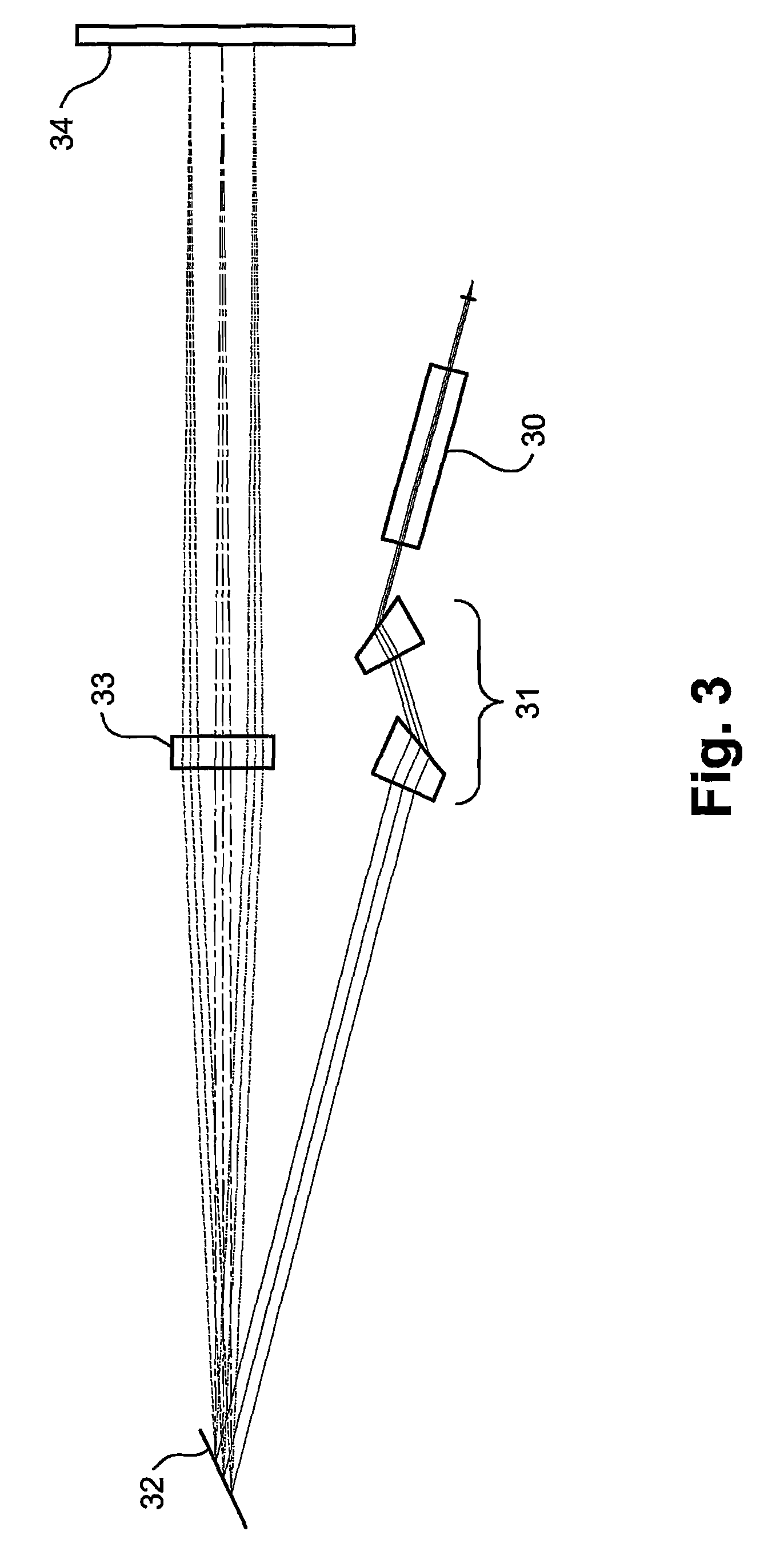
[0015]Alternatively and preferably, the beam steering can be performed by utilizing a set of serially disposed liquid crystal arrays and prismatic polarization separators, such as wedge shaped birefringent walk-off crystals, which generate different angles of propagation to the beam passing therethrough, according to the different polarizations of the beams produced by the setting of the liquid crystal array pixels. The steered angle of a beam passing through a particular liquid crystal pixel is determined by the polarization rotation setting of each of the serial LC pixels through which the beam passes. This embodiment has the advantage of generating the beam steering without any moving parts, but the disadvantage of a more complex control system and possibly higher cross-talk between channels.
[0034]In accordance with still another preferred embodiment of the present invention, there is further provided a method of switching selected wavelength components of a multi-wavelength input optical signal to a desired output port, the method comprising the steps of:(i) generating at least one beam from the multi-wavelength input optical signal(ii) laterally expanding the at least one multi-wavelength optical beam in a predetermined plane,(iii) spatially dispersing in the predetermined plane the at least one multi-wavelength optical beam to generate wavelength components thereof,(iv) providing a pixilated beam attenuating array to attenuate the dispersed wavelength components, and(vi) steering at least one of the dispersed wavelength components towards a desired output port,wherein the steering is performed in co-operation with the attenuation in such a manner that the steered beam is prevented from coupling into any output ports other than its desired output port.

Problems solved by technology

Additionally, the light of a specific wavelength can be blocked, in which case the beam steering is unused.

Method used


Image

  • Optical wavelength selective router
  • Optical wavelength selective router
  • Optical wavelength selective router

Examples


Embodiment Construction

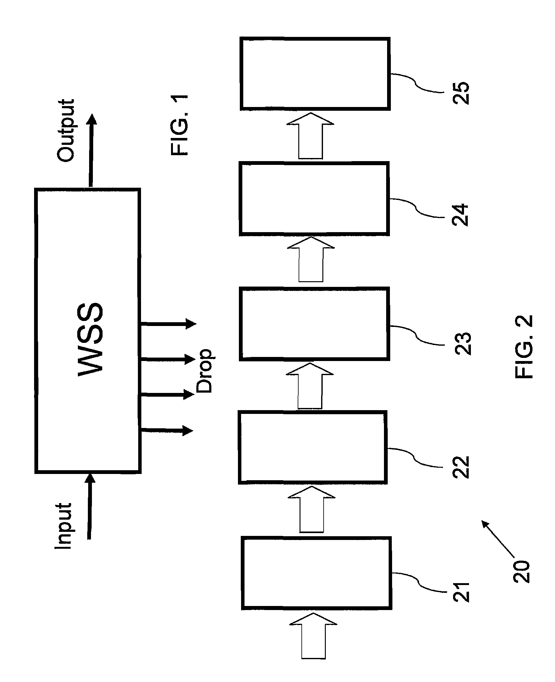
[0055]Reference is now made to FIG. 1, which illustrates schematically a block diagram of the functionality of an optical wavelength router, including a single input port, a single main output port and a number of Drop ports. The function of the router is to either transmit, to block or to attenuate any wavelength channel in the input signal, and to direct that signal, if transmitted or attenuated, to any of the output or Drop ports.

[0056]Reference is now made to FIG. 2, which illustrates schematically the router 20 of FIG. 1, as implemented according to a preferred embodiment of the present invention, in the form of a block diagram of the functionality of the separate operative parts of the router. The signals are input to the router through a Fiber Interface Block 21, which accepts the input signals and converts them into free-space beams for polarization processing, lateral expansion and spatial manipulation. According to a preferred embodiment of the present invention, the free-...


PUM


Abstract

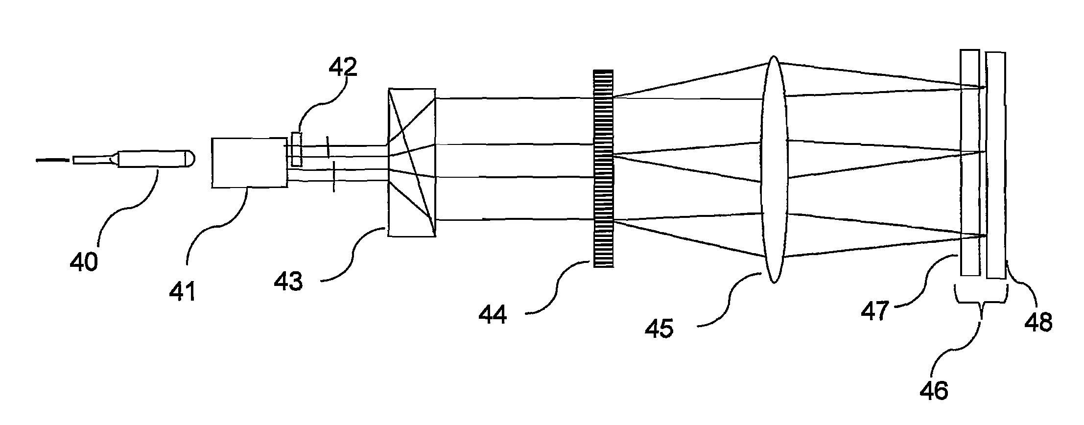
A fiber-optical, wavelength selective switch, especially for channel routing with equalization and blocking applications. The input signals are converted to light beams having predefined polarizations (41). The beams are then laterally expanded (43), and then undergo spatial dispersion in the beam expansion plane. The different wavelength components are directed through a polarization rotation device, pixilated along the wavelength dispersion direction such that each pixel operates on a separate wavelength. Each beam is passed into a pixilated beam steering array (48), for directing each wavelength to a desired output port. The beam steering devices can be MEMS-based or Liquid crystal-based, or an LCOS array. When the appropriate voltage is applied to a pixel and its associated beam steering element, the polarization of the light passing through the pixel is rotated and the beam steered to couple to the selected output port.

Description

[0001]This application is the U.S. national phase of International Application No. PCT / IL2006 / 001052 filed Sept. 10, 2006, which claims priority from U.S. Provisional Application No. 60 / 715,695, filed Sept. 8, 2005. The International Application was published in English on Mar. 15, 2007 as WO 2007 / 029260 Aunder PCT Article 21(2).FIELD OF THE INVENTION[0002]The present invention relates to the field of fast optical switches, whose operation is wavelength dependent, especially for use as a wavelength selective router or channel blocker in an optical communication system.BACKGROUND OF THE INVENTION[0003]It is known in the field of optical communications to use optical wavelengths as optical carriers for carrying digital or analog information. Also, the different wavelengths may be used to discriminate one set or channel of information from another. When a plurality of wavelengths are coupled or multiplexed onto a single fiber, this is called wavelength division multiplexing (WDM). Use...

Claims


Application Information

Patent Timeline
Patent Type & Authority Patents(United States)
IPC IPC(8): G02B6/26
CPCG02B6/2713G02B6/29311G02B6/29313G02B6/29383G02B6/356H04Q11/0005G02B6/3512G02B6/3548G02B6/3594H04J14/0212H04J14/0219H04Q2011/003H04Q2011/0035
Inventor COHEN, GILSUH, SEONGWOOCOREM, YOSSI
Owner II VI DELAWARE INC
Why Eureka
Try Eureka