Sample holder for dynamic light scattering

a dynamic light scattering and sample holder technology, applied in the direction of biochemistry equipment, biochemistry equipment and processes, material testing goods, etc., can solve the problems of inefficient placement of heating or cooling elements, prior-art designs that fail to optimize both optical access and heat transfer, and achieve efficient and uniform heat transfer, facilitate loading, holding and unloading, and facilitate sample cooling

Inactive Publication Date: 2010-11-30
CANADIAN BLOOD SERVICES
View PDF38 Cites 2 Cited by
  • Summary
  • Abstract
  • Description
  • Claims
  • Application Information

AI Technical Summary

Benefits of technology

[0010]It is therefore an object of the present invention to provide a sample holder that overcomes at least one of the deficiencies of the prior art. The sample holder (or sample-holding device) has a base including a stationary upright wall or “backing member”. A movable upright member or “clamping member” can be displaced relative, e.g. by sliding over a rail, so as to gently clamp or grip a capillary, cuvette, tube or other fluid container between the two members or walls. This design facilitates the loading, holding and unloading of variously sized capillaries, cuvettes or other such fluid sample containers. The sample holder further includes heating / cooling elements mounted on each wall or upright member. In one embodiment, the heating / cooling elements are mounted between the wall (or upright member) and a respective grooved, heat-conductive plate which has opposed, inwardly facing grooves for gripping the fluid container to preferably hold the container in a substantially vertical orientation. The heating / cooling elements can be made to extend the full height of the plates and walls (upright members) to provide efficient and uniform heat transfer to and from the fluid sample in the sample holder. In one embodiment, the sample holder includes finned heat sinks and fans to facilitate cooling of the sample. In order to enhance optical access to the fluid sample, substantially horizontal slots are provided in the walls (upright members), in the heating / cooling elements and in the plates.
[0011]This sample holder can therefore be integrated into a dynamic light scattering (DLS) system for collecting scattered light from a variety of locations around the sample. Therefore, a DLS system using this sample holder can operate with a single light source, such as a single laser diode, while collecting scattered light by deploying a plurality of light collectors at various locations around the sample holder. This versatile, easy-to-use and efficient sample holder greatly facilitates DLS / QELS or other optical analysis techniques for analyzing platelet solutions, whole blood or other colloids or colloidal dispersions.
[0021]In yet a further embodiment, the holding device includes a first pair of heat-conductive plates connected to inwardly facing surfaces of the first pair of heating / cooling elements, the first pair of plates having an inwardly facing groove for gripping the container over a substantial surface of the container for efficiently conducting heat to or from the container; and a second pair of heat-conductive plates connected to inwardly facing surfaces of the second pair of heating / cooling elements, the second pair of plates having an inwardly facing groove for gripping the container over a substantial surface of the container for efficiently conducting heat to or from the container.

Problems solved by technology

However, to the extent of Applicant's knowledge, each of these prior-art sample holders is only designed to hold a specific type of container (i.e. either a round capillary or a square cuvette) and furthermore is only designed to only hold a container of a specific size or of a very limited size range.
However, these prior-art temperature-controlled sample holders are not designed for efficient and uniform heat transfer because they must provide optical access for both the incident light and the scattered light.
In other words, heating or cooling elements are located inefficiently (such as beneath the container) in order to ensure that there is adequate optical access.
The prior-art designs have in general failed to optimize both optical access and heat transfer.

Method used


Image

  • Sample holder for dynamic light scattering
  • Sample holder for dynamic light scattering
  • Sample holder for dynamic light scattering

Examples


Embodiment Construction

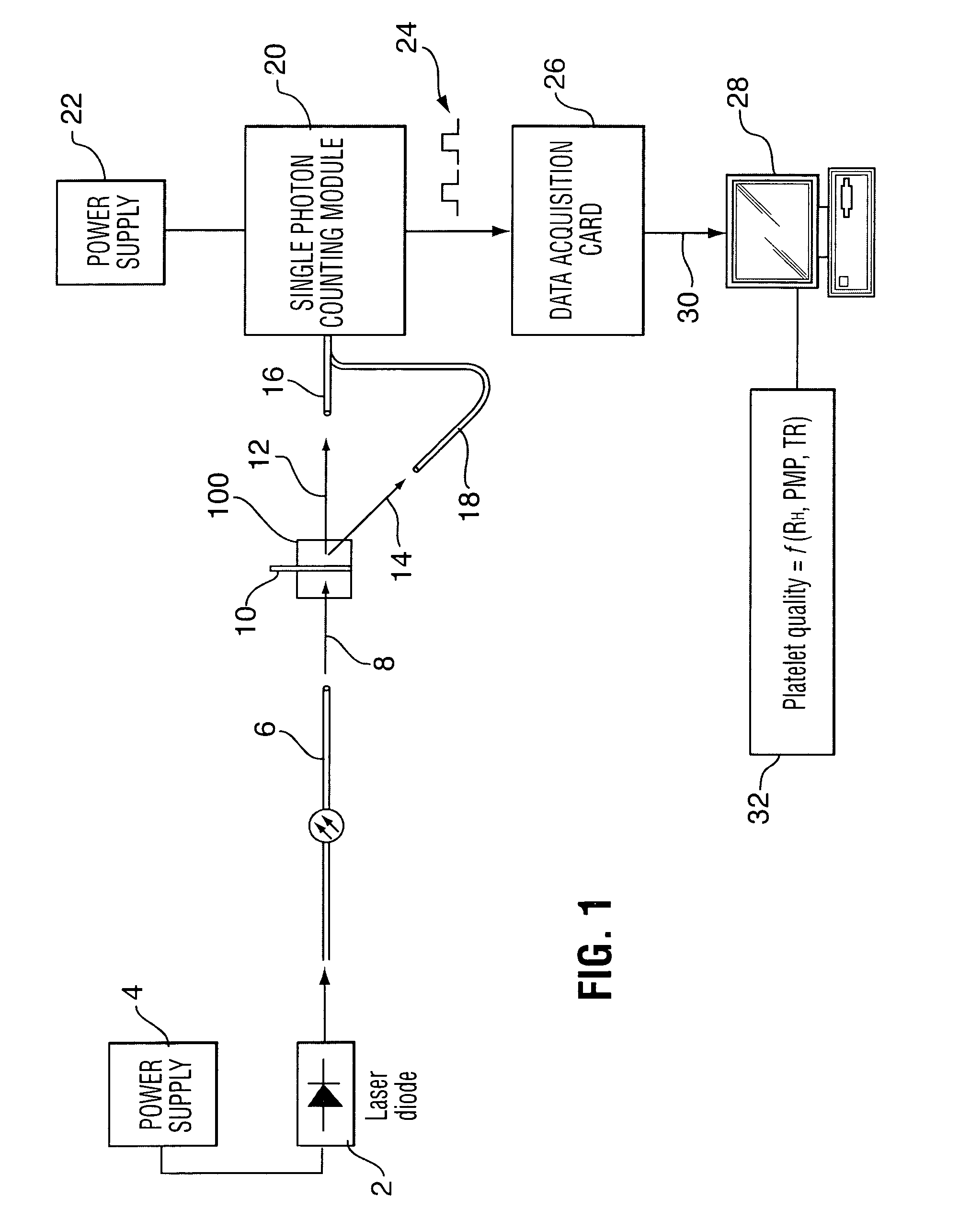
[0035]FIG. 1 is a schematic view of a system for dynamic light scattering (DLS), which is also known as quasi-elastic light scattering (QELS). As shown in FIG. 1, the system has a light source such as, for example, a laser diode 2 which is powered by a power source, as is well known in the art. The laser diode 2 generates and emits a beam of laser light into a length of optical fiber 6. The laser preferably generates light at 635 nm although other wavelengths could be used, as would be appreciated by those of ordinary skill in the art. As is also known in the art, the intensity of the laser beam can be adjusted using an adjustable neutral density filter (or by using an attenuator in the fiber) which allows the laser to be operated at maximum power while curtailing the intensity of the incident light. This reduces multiple scattering and other undesirable optical effects that arise when the intensity of the incident light is too high. The optical fiber can be single-mode, polarizatio...


PUM

PropertyMeasurementUnit
outer diameteraaaaaaaaaa
wavelengthsaaaaaaaaaa
volumeaaaaaaaaaa

Abstract

A sample holder holds various sizes of capillaries or cuvettes for use in dynamic light scattering (DLS) or quasi-elastic light scattering (QELS), such as in DLS of fluid samples such as platelet solutions, whole blood, colloids or the like. The sample holder has a base with a stationary backing member and a sliding, rail-mounted clamping member that is magnetically biased toward the backing member. The sample holder has Peltier-type thermoelectric heating / cooling elements that extend the full height of the clamping and backing members to optimize heat transfer efficiency. The sample holder further includes horizontal slots that enable collection of scattered light from various angles around the device. Finned heat sinks are mounted above and below the horizontal slots on the outwardly facing surfaces of the backing and clamping members to stabilize the temperature of the fluid sample in the sample holder without interfering with incident or scattered light.

Description

CROSS-REFERENCE TO RELATED APPLICATIONS[0001]This is the first application filed for the present invention.MICROFICHE APPENDIX[0002]Not Applicable.TECHNICAL FIELD[0003]The present invention relates generally to optical analysis of fluids, colloidal dispersions or suspensions and, in particular, to sample-holding devices for dynamic light scattering (DLS) or quasi-elastic light scattering (QELS).BACKGROUND OF THE INVENTION[0004]Dynamic light scattering (DLS), which is also known as quasi-elastic light scattering (QELS), is an optical analysis technique that is well known in the art. An optical source such as laser light is focused into the sample. Light scatters when it hits particles suspended in the fluid, such as platelets suspended in solution. The scattered light is collected by light collectors disposed at specific angles relative to the incident light. As is known in the art, the scattered light fluctuates due to Brownian motion of the particles in solution. Using algorithms t...

Claims


Application Information

Patent Timeline
Patent Type & Authority Patents(United States)
IPC IPC(8): B01L3/00F25B29/00G01N21/00G01N15/02G01N21/01B01L9/00G01N31/00
CPCG01N21/0332G01N21/51Y10T436/101666
Inventor MAURER, ELISABETHMAURER, GEORGBROWN, KEDDIE
Owner CANADIAN BLOOD SERVICES
Why Eureka
Try Eureka