Light source that utilizes small footprint reference gas cells for multiple laser frequency stabilization

a reference gas cell and laser frequency stabilization technology, applied in semiconductor lasers, laser cooling arrangements, laser details, etc., can solve the problems of servo mechanism, source emission spectrum too broad for many applications, limited power available from a single semiconductor laser, etc., to reduce temperature fluctuations and reduce differences.

Active Publication Date: 2010-11-30
KEYSIGHT TECH
View PDF5 Cites 5 Cited by
  • Summary
  • Abstract
  • Description
  • Claims
  • Application Information

AI Technical Summary

Benefits of technology

[0011]In one embodiment, each of the absorption cells also includes a buffer gas that reduces diffusion of gas from one of the absorption cells into the other of the absorption cells. The buffer gas is chemically inert with respect to the absorption gas and does not have an optical transmission as a function of wavelength that varies with wavelength significantly at wavelengths near the output wavelength. In another embodiment, the buffer gas quenches fluorescence of the absorption gas.
[0012]In one embodiment, the environmental control system includes a housing surrounding the absorption cells. The housing includes a temperature control system that reduces temperature fluctuations within the housing. In one embodiment, the housing includes an electromagnetic field generator that reduces differences in the electromagnetic fields in each of the absorption cells.

Problems solved by technology

The power available from a single semiconductor laser is limited.
Unfortunately, the individual laser diodes emit light at slightly different wavelengths, and hence, the resulting light source has an emission spectrum that is too broad for many applications.
Unfortunately, the wavelength at which the cell has an absorption maximum depends on a number of factors in addition to the type of absorption gas in the cell.
Since these additional factors can vary from cell to cell, this type of servo mechanism presents problems when multiple cells are used to control multiple lasers.
However, this approach increases the cost of the servo loop.
Furthermore, the servo mechanism must be insensitive to fluctuations in the power output of the laser and fluctuations in the polarization of the laser output.

Method used


Image

  • Light source that utilizes small footprint reference gas cells for multiple laser frequency stabilization
  • Light source that utilizes small footprint reference gas cells for multiple laser frequency stabilization
  • Light source that utilizes small footprint reference gas cells for multiple laser frequency stabilization

Examples


Embodiment Construction

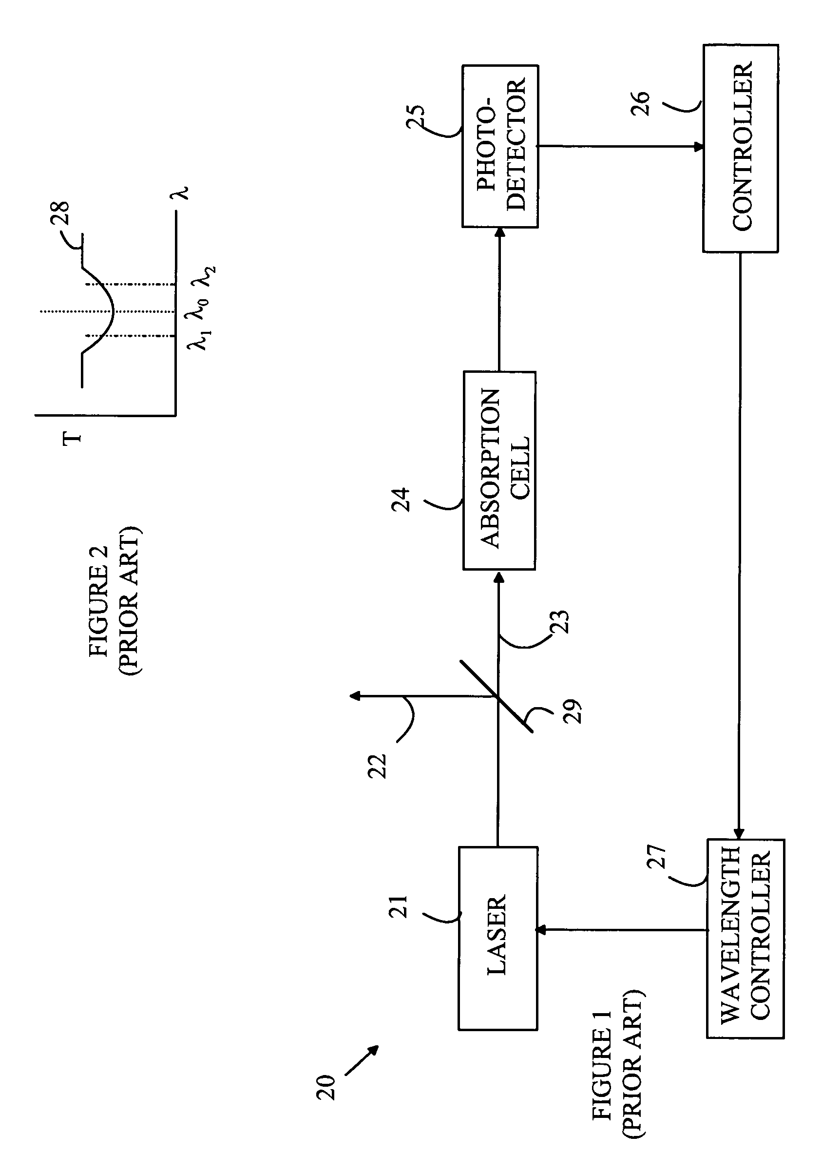
[0020]The manner in which the present invention provides its advantages can be more easily understood with reference to FIGS. 1 and 2, which illustrate a typical prior art light source that utilizes a wavelength servo system. In the following discussions, the absorbent maximum is used as an example. But embodiments can also be constructed that utilize a local absorbent minimum. Light source 20 utilizes a laser 21 that has an output wavelength that can be controlled by appropriate signals to a wavelength controller 27. The output beam from laser 21 is split into two beams 22 and 23 by a beam splitter 29, the majority of the power being devoted to beam 22. Beam 23 is directed into an absorption cell 24 that contains an absorption gas having an absorption line centered at the desired wavelength, λ0. The intensity of the light in beam 23 after that beams passes through the absorption gas is detected by photodetector 25. The output of photodetector 25 as a function of wavelength is illus...


PUM


Abstract

A light source and the method for operating the same are disclosed. The light source includes first and second lasers, and first and second wavelength control assemblies. The lasers emit first and second light beams, respectively, at wavelengths that are determined by first and second wavelength control signals. First and second beam splitters split the first and second light beams, respectively, to create first and second sampling light beams. The first and second wavelength control assemblies receive sampling light beams and generate the first and second wavelength control signals such that the wavelengths of the first and second light beams differ by no more than a predetermined amount. The first and second wavelength control assemblies each include an absorption cell having a gas that has an optical absorption that varies with the wavelength of the first and second sampling light beams at wavelengths around the output wavelength of the light source.

Description

BACKGROUND OF THE INVENTION[0001]The power available from a single semiconductor laser is limited. In many applications, power levels in excess of one watt are required. For example, communication applications at wavelengths of about 1.5 micrometers (μm) can require more power than the power that can be provided by a single laser diode.[0002]In principle, the light from a number of laser diodes of the same type can be combined to provide a light source with an output power level greater than the power level that can be obtained with a single laser. Unfortunately, the individual laser diodes emit light at slightly different wavelengths, and hence, the resulting light source has an emission spectrum that is too broad for many applications.[0003]To overcome this problem, some form of servo loop could, in principle, be utilized to tune each of the individual laser diodes to the desired frequency. In such a system, a portion of the output laser light from the laser diode to be regulated ...

Claims


Application Information

Patent Timeline
Patent Type & Authority Patents(United States)
IPC IPC(8): H01S3/10
CPCH01S5/0687H01S5/005H01S5/06837H01S5/4025
Inventor JOHNSTONE, ERIC STEPHENZHU, MIAORANGANATH, TIRUMALA R.
Owner KEYSIGHT TECH
Why Eureka
Try Eureka