Lithography mask design through mask functional optimization and spatial frequency analysis

a functional optimization and spatial frequency analysis technology, applied in the field of electronic design automation, can solve problems such as adding a cost related problem

Active Publication Date: 2010-12-21
D2S
View PDF26 Cites 23 Cited by
  • Summary
  • Abstract
  • Description
  • Claims
  • Application Information

AI Technical Summary

Benefits of technology

[0013]The present invention expresses the desirability of a given mask function as a functional (a mathematical form that is a function of a function over a defined region) that calculates the “cost” with respect to the predicted printed image and possibly various a priori mask constraints. Since the present invention expresses the mask with an exact analytical form, the cost and its functional derivatives can be evaluated analytically and consistently, which enables the use of efficient cost minimization algorithms.

Problems solved by technology

Unless the mask representation automatically satisfies all desired mask constraints and characteristics, such as allowed transmission values or minimum feature size, the formula measuring a mask's suitability will introduce terms that add a cost related to the violation of these constraints.

Method used


Image

  • Lithography mask design through mask functional optimization and spatial frequency analysis
  • Lithography mask design through mask functional optimization and spatial frequency analysis
  • Lithography mask design through mask functional optimization and spatial frequency analysis

Examples


Embodiment Construction

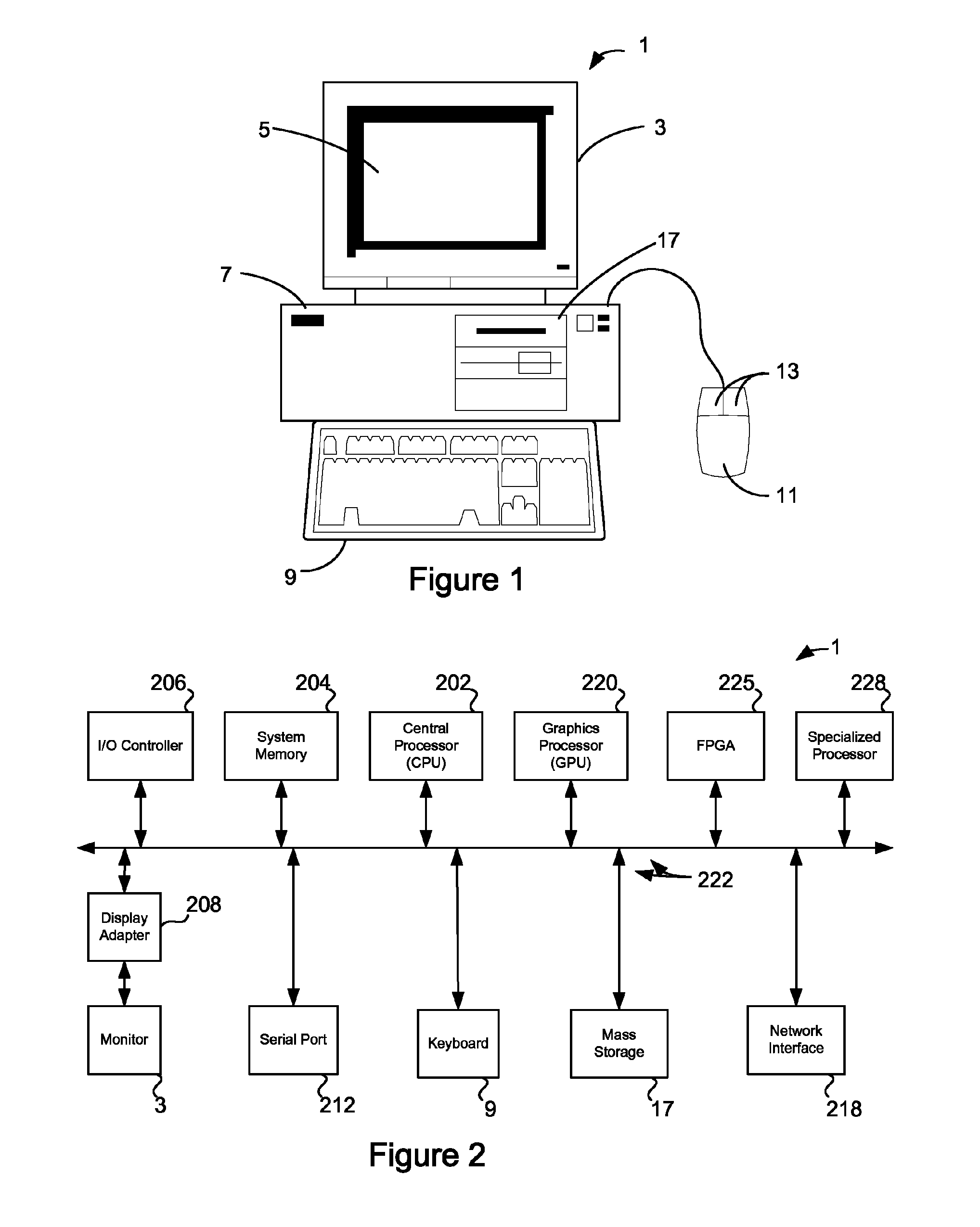
[0027]FIG. 1 shows a system of the present invention. In an embodiment, the invention is software that executes on a computer workstation system, such as shown in FIG. 1. FIG. 1 shows a computer system 1 that includes a monitor 3, screen 5, cabinet 7, keyboard 9, and mouse 11. Mouse 11 may have one or more buttons such as mouse buttons 13. Cabinet 7 houses familiar computer components, some of which are not shown, such as a processor, memory, mass storage devices 17, and the like.

[0028]Mass storage devices 17 may include mass disk drives, floppy disks, magnetic disks, optical disks, magneto-optical disks, fixed disks, hard disks, CD-ROMs, recordable CDs, DVDs, recordable DVDs (e.g., DVD-R, DVD+R, DVD-RW, DVD+RW, HD-DVD, or Blu-ray Disc), flash and other nonvolatile solid-state storage (e.g., USB flash drive), battery-backed-up volatile memory, tape storage, reader, and other similar media, and combinations of these.

[0029]A computer-implemented or computer-executable version of the i...


PUM

PropertyMeasurementUnit
geometric shapesaaaaaaaaaa
frequency spaceaaaaaaaaaa
frequency space representationaaaaaaaaaa

Abstract

In an electronic design automation technique for optical proximity correction, a mask is represented by a function with an exact analytical form over a mask region. Using the physics of optical projection, a solution based on a spatial frequency analysis is determined. Spatial frequencies above a cutoff are determined by the optical system do not contribute to the projected image. Spatial frequencies below this cutoff affect the print (and the mask), while those above the cutoff only affect the mask. Frequency components in the function below this cutoff frequency may be removed, which will help to reduce computational complexity.

Description

CROSS-REFERENCE TO RELATED APPLICATION[0001]This patent application claims the benefit of U.S. provisional patent application 60 / 827,295, filed Sep. 28, 2006, which is incorporated by reference along with all other references cited in this application.BACKGROUND OF THE INVENTION[0002]This invention relates to the field of electronic design automation, and in particular, the optimization of masks used for photolithographic printing of circuit designs, known in the field as optical proximity correction.[0003]Production-scale chip manufacturing uses photolithographic techniques to build up layers of materials on a wafer to create the transistors, wires, and so on, that realize a chip design. The sizes of the features to be printed on the wafer are approaching the limits set by the wavelength of the light, the optical projection system, and the behavior of the light sensitive materials used, among many other factors.[0004]Diffraction effects from the wavelength of the light source and t...

Claims


Application Information

Patent Timeline
Patent Type & Authority Patents(United States)
IPC IPC(8): G06F17/50G06K9/00G21K5/00G03F1/00G06F17/14G06F19/00G06F40/00
CPCG03F1/50G06F17/50G03F1/70G03F1/28G06F30/00G06F30/39G06F30/398G06F2111/10G06F2119/18G03F1/00G06F17/14G21K5/00
Inventor UNGAR, P. JEFFREYTORUNOGLU, ILHAMI H.
Owner D2S
Why Eureka
Try Eureka