
Method and device for decoding a signal

a signal and signal technology, applied in the field of signal decoding methods, can solve the problems of adverse effect on the emc response require more sophisticated and thus more expensive components, and high demands on the transmission channel, and achieve high transmission rate, high reliability, and high availability of the data transmission system.

Inactive Publication Date: 2011-01-04
ROBERT BOSCH GMBH
View PDF10 Cites 8 Cited by
  • Summary
  • Abstract
  • Description
  • Claims
  • Application Information

AI Technical Summary

Benefits of technology

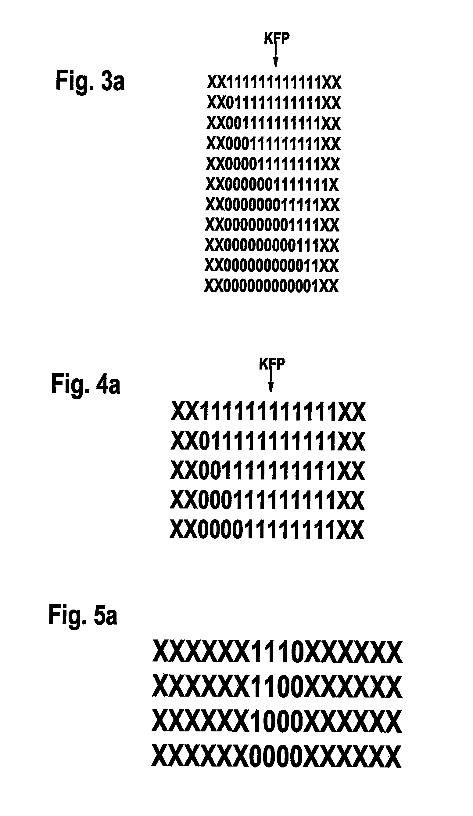
The present invention provides a method for transmitting data at a high transmission rate, with high reliability and availability of the data transmission system. The method involves determining the potential edge change of a signal at a receiving user and sampling the signal at a n-fold oversampling. The sampled values are compared to corresponding values that were determined previously and stored, and the value of the bit received between two potential edge changes is determined as a function of the result of the comparison. The method utilizes early sampling and multiple edge acceptance vectors to accurately detect and assign an edge change to its potential edge position. The method is applicable to various data transmission systems and can be easily transferred to different systems.

Problems solved by technology

This is difficult especially when the sampling instant refers to an edge of the signal and also analyzes a plurality of binary data values (bits) of the transmitter relative thereto, over many periods of the sampling period.
It has become apparent that the rigid specification of the sampling instant without considering the asymmetrical delays on the different transmission paths leads to problems.
Because of the rigid selection of the sampling instant per bit (for instance, at n=8 sampling values per bit, to 5, in the middle of a bit), both the influence of the asymmetrical distortion and the frequency deviation as well as the additional time discretization by the sampling pose a problem and place high demands on the transmission channel.
Increasing the edge steepness so as to reduce the asymmetrical delays would indeed be advantageous for the timing, but on the other hand would require technically more sophisticated and thus more expensive components and, in addition, could have an adverse effect on the EMC response of the data transmission system.
However, depending on the pulse distortion, there is the risk of evaluating the wrong datum either on the one or the other bit boundary.
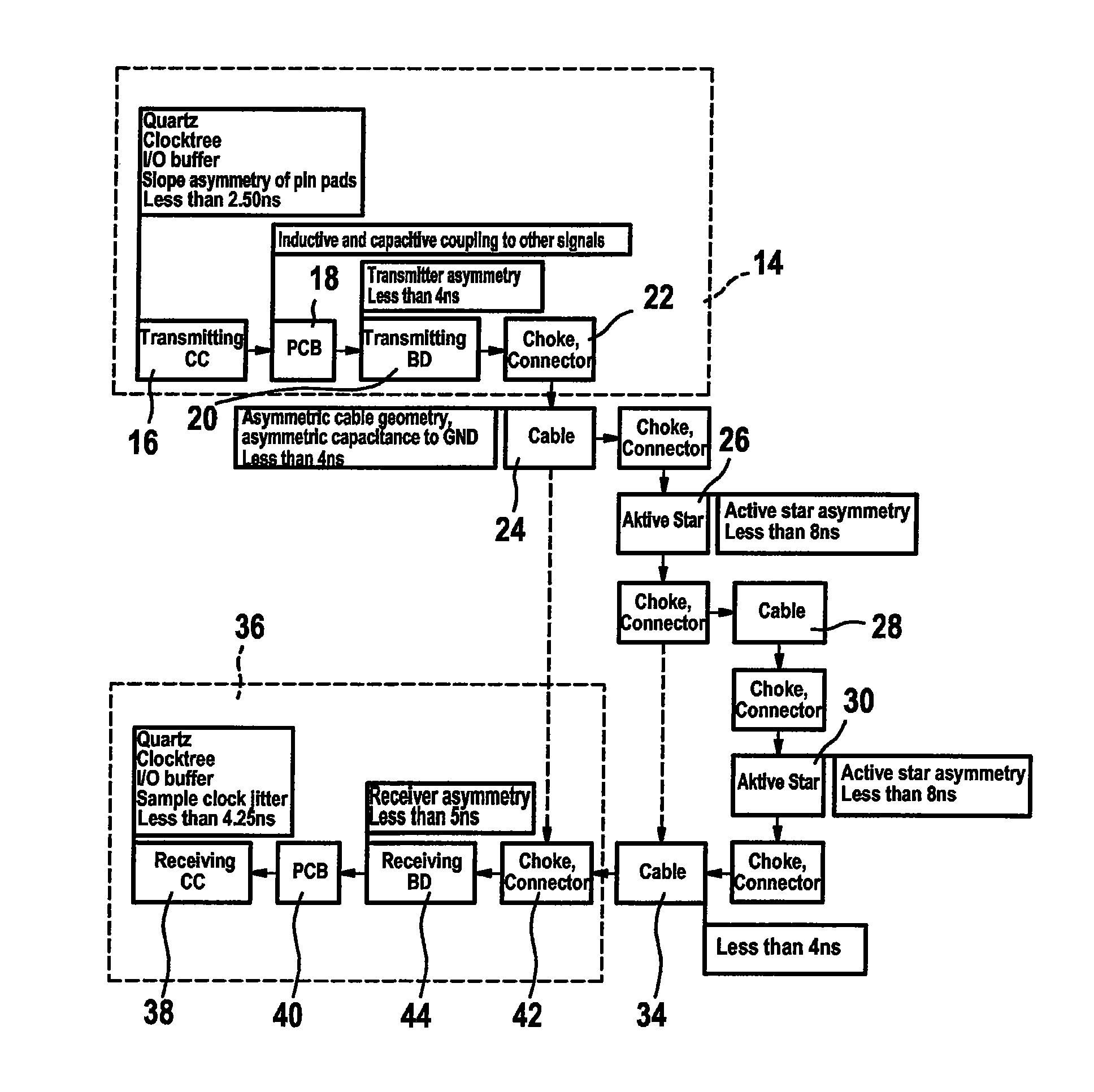
When realizing FlexRay data transmission systems, in particular in the case of complex systems that include a plurality of star couplers and passive networks, it has also been shown that the asymmetrical delay times that occur there are so great that they exceed a time budget specified by the FlexRay protocol.
However, as may be the case in complex network topologies, if the asymmetrical delay exceeds the provided time budget, then an incorrect value will be determined in a sampling at the fifth sampling cycle (counter reading of the cycle counter at 5), since the particular bit that should actually have been sampled was already available at an earlier instant due to the asymmetrical delay and is no longer present because of the early edge change.
Exceeding the time budget in the advance or retard direction results in decoding errors, which means that incorrect data are received.
However, if the error detection algorithm responds too frequently, there is the disadvantage of reduced availability of the data transmission system.
However, this should not be understood as a restriction.

Method used


Image

  • Method and device for decoding a signal
  • Method and device for decoding a signal
  • Method and device for decoding a signal

Examples


Embodiment Construction

[0051]The networking of control devices, sensor systems and actuator systems with the aid of a communications system and a communications link such as a bus system, has increased drastically in recent years in the construction of modern motor vehicles or also in machine construction, especially in the field of machine tools, and in automation as well. In this context, synergistic effects may be achieved by distributing functions to a plurality of control devices. These are referred to as distributed systems.

[0052]The communication between various users of such a data transmission system is increasingly being implemented via a bus system. The communication traffic on the bus system, access and receiving mechanisms, as well as error handling are regulated by a protocol. One known protocol is, for instance, the FlexRay protocol, which is currently based on the FlexRay protocol specification v2.1. FlexRay is a rapid, deterministic and error-tolerant bus system, especially for the use in...


PUM


Abstract

A method and a device for decoding a signal transmitted via at least one transmission line of a data transmission system, in a user of the data transmission system receiving the signal. Instead of at discrete instants, as currently done, sampling at a specific sampling instant does not take place. To this end, a potential-edge position (PEP) for an imminent edge is estimated first. Then, given n-fold oversampling, maximally n sampling values before the PEP and maximally n sampling values after the PEP are determined and compared with previously recorded and stored sampling values. The stored sampling values are preferably stored in an edge-acceptance vector (EAV) and correspond to an edge change of the signal to be decoded at a particular point in time. Preferably not all detected 2n sampling values are compared to the content of the EAVs, but the comparison is limited to a portion, combined to a sensitivity range, of the 2n sampling values of each EAV.

Description

FIELD OF THE INVENTION[0001]The present invention relates to a method for decoding a signal, transmitted via at least one transmission line of a data transmission system, in a user of the data transmission system receiving the signal. Furthermore, the present invention relates to a method for decoding a signal. In addition, the present invention relates to a system for transmitting data. Furthermore, the present invention relates to a user of a data transmission system. Finally, the present invention also relates to a communications controller of a user of a data transmission system.BACKGROUND INFORMATION[0002]The networking of control units, sensor systems and actuator systems with the aid of a communications system and a communication connection, for instance in the form of a bus system, has increased drastically in recent years in the manufacture of modern motor vehicles or also in machine construction, especially in the field of machine tools, and in the automation field as well...

Claims


Application Information

Patent Timeline
Patent Type & Authority Patents(United States)
IPC IPC(8): H03M7/34
CPCH04L7/0331H04L7/044H04L27/00G06F13/38H04L1/00
Inventor ROHATSCHEK, ANDREAS-JUERGEN
Owner ROBERT BOSCH GMBH
Learn More