Zero voltage switching coupled inductor boost power converters

a technology of inductance boost and zero voltage, applied in the direction of electric variable regulation, process and machine control, instruments, etc., can solve the problem of transferring net energy from its primary circuit to its secondary circuit, and achieve the effect of reducing overall component stress factors, reducing electromagnetic interference, and high efficiency

Inactive Publication Date: 2011-01-04
WITTENBREDER JR ERNEST HENRY
View PDF13 Cites 10 Cited by
  • Summary
  • Abstract
  • Description
  • Claims
  • Application Information

AI Technical Summary

Benefits of technology

[0006]An object of the subject invention is to reveal a new beneficial power conversion circuit with higher efficiency and lower electromagnetic interference.
[0007]Further objects and advantages of my invention will become apparent from a consideration of the drawings and ensuing d

Problems solved by technology

One disadvantage of the ZVS flyback is that it transfers net energy from its primary ci

Method used


Image

  • Zero voltage switching coupled inductor boost power converters
  • Zero voltage switching coupled inductor boost power converters
  • Zero voltage switching coupled inductor boost power converters

Examples


Embodiment Construction

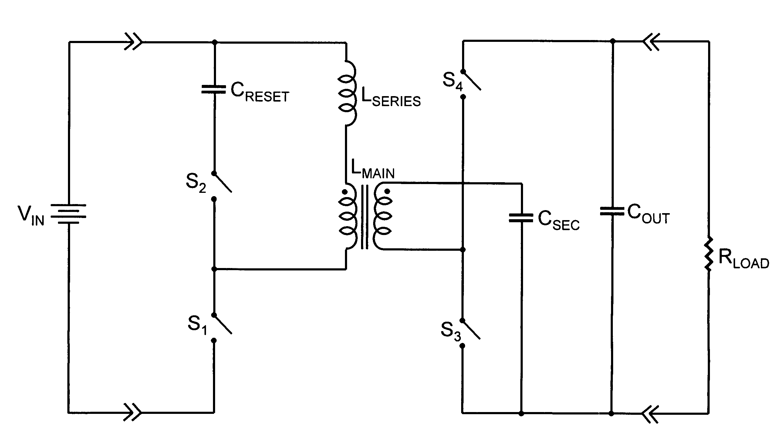
[0025]FIG. 6 illustrates a ZVS coupled inductor boost power converter according to the subject invention. A first terminal of an input source of dc power and voltage is connected to a first terminal of a capacitor CRESET and to a dotted terminal of a primary winding of a coupled inductor LMAIN which has a substantial amount of leakage inductance and leakage flux due to its construction. Leakage inductance is the inductance associated with leakage flux which is flux generated in one winding that is not magnetically coupled to the other winding. The coupled inductor LMAIN is constructed in a manner typical of a flyback transformer having a core made from a magnetically permeable material with a substantial amount of energy storage capability, either by having a discrete air gap in its core or a distributed air gap throughout its core or some combination thereof. A second terminal of the input source of dc power and voltage is connected to a first terminal of a switch S1. A second term...


PUM


Abstract

The subject invention reveals a new coupled inductor boost converter which achieves zero voltage turn on switching for all four circuit switches. The coupled inductor of the circuit is fully clamped and thereby achieves excellent noise performance with neither snubbers nor clamps. The new coupled inductor boost converter is outstanding for isolated high voltage applications because the voltage stress of the secondary switches does not exceed the output voltage, it requires only one magnetic circuit element, and the average voltage stress of the secondary winding is equal to or less than half the output voltage.

Description

CROSS REFERENCE TO RELATED APPLICATIONS[0001]This application claims the benefit of PPA Ser. No. 60 / 766,547, filed 2006 Jan. 26 by the present inventor. This application is a continuation in part of application Ser. No. 11 / 626,908 filed Jan. 25, 2007 now U.S. Pat. No. 7,551,459.BACKGROUND OF THE INVENTION[0002]1. Field of the Invention[0003]The subject invention generally pertains to electronic power conversion circuits, and, more specifically, to high frequency, switched mode electronic power converters. The subject matter relates to new isolated power converters which achieve higher efficiency compared to prior art power converters.[0004]2. Description of Related Art[0005]Often a power conversion circuit such as a ZVS flyback converter, as illustrated in FIG. 1, is used to convert power efficiently at high switching frequencies. The efficiency advantage of the ZVS Flyback converter relates to its relative simplicity and its ability to achieve zero voltage switching over a broad ra...

Claims


Application Information

Patent Timeline
IPC IPC(8): H02M3/335
CPCH02M3/33576H02M2001/0048Y02B70/1491H02M1/0048H02M7/05Y02B70/10
Inventor WITTENBREDER, JR., ERNEST HENRY
Owner WITTENBREDER JR ERNEST HENRY
Why Eureka
Try Eureka