
Biosensor with multiple electrical functionalities

a biosensor and functional technology, applied in the field of electrically operable biosensors, can solve the problems of inaccurate blood glucose measurement accuracy, confounding variables in the electrochemical methods of measuring the concentration of a chemical in blood, and the effect of confounding variables in the blood glucose measurement, so as to reduce the size of the electrical pattern, increase production speed, and enhance the quality and complexity of the electrical pattern

Inactive Publication Date: 2011-01-11
ROCHE DIABETES CARE INC
View PDF60 Cites 40 Cited by
  • Summary
  • Abstract
  • Description
  • Claims
  • Application Information

AI Technical Summary

Benefits of technology

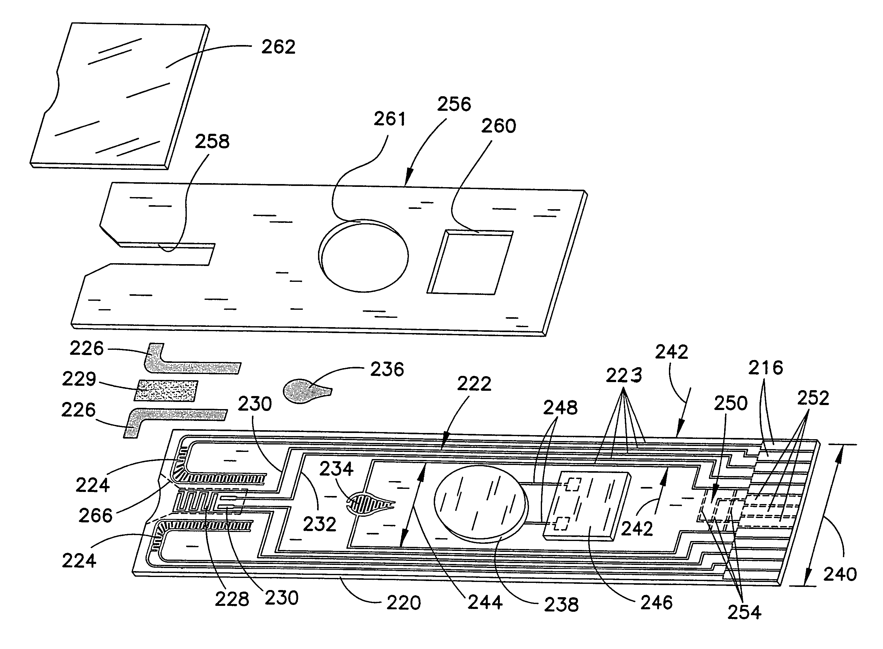
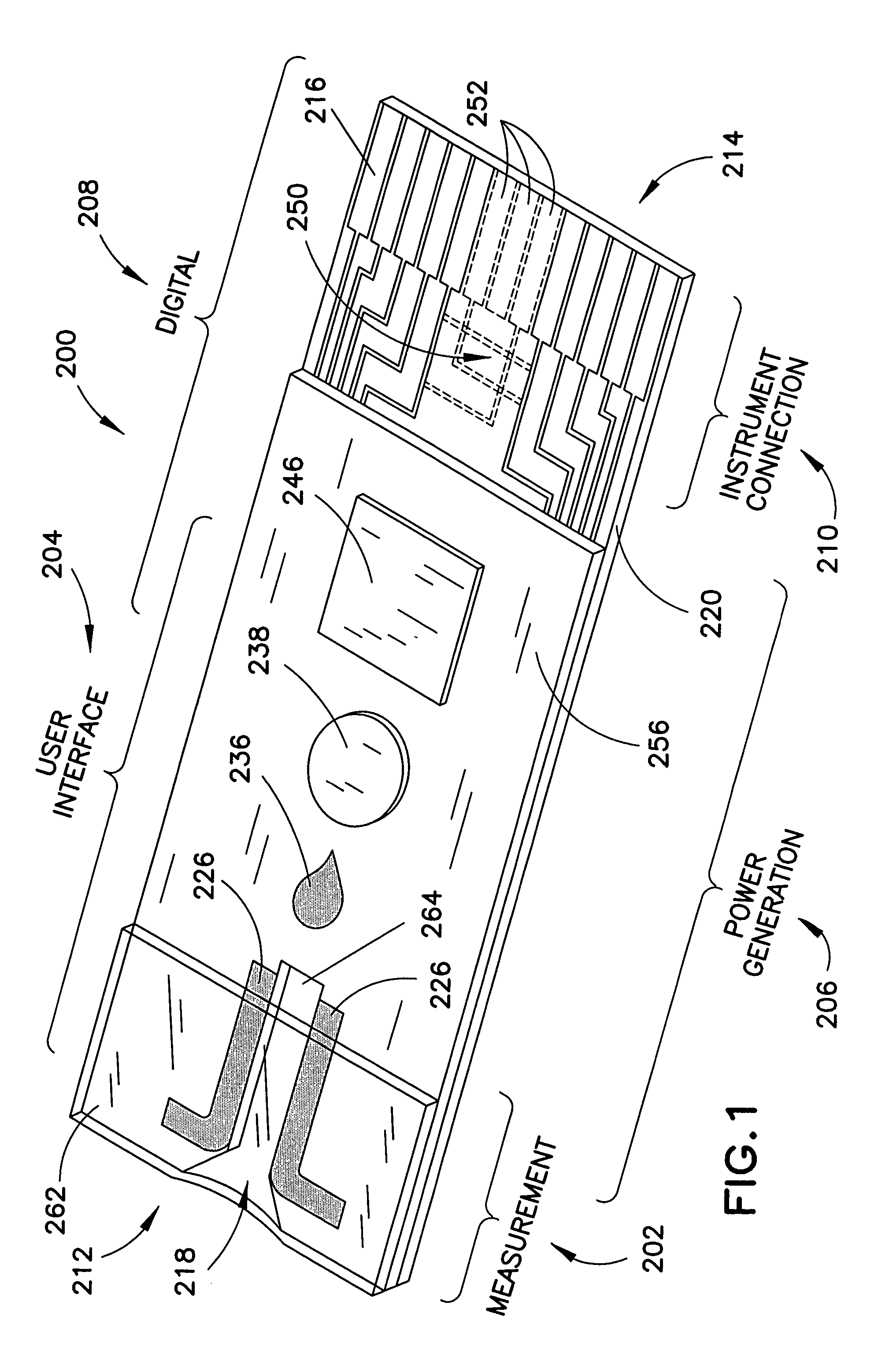
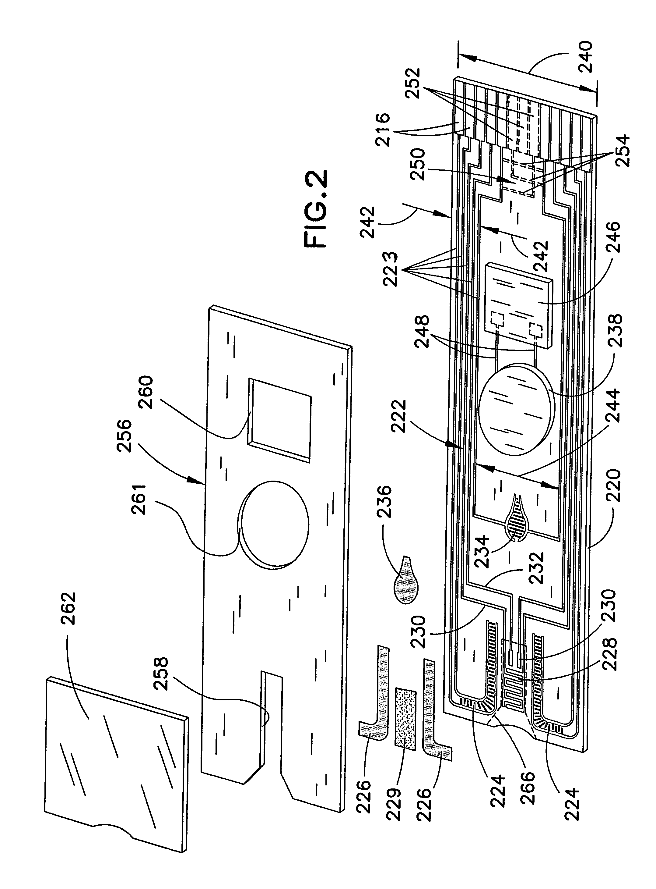
The present invention provides a biosensor with multiple electrical functionalities located both within and outside of the measurement zone in which the fluid sample is interrogated. The biosensor has an enhanced electrical pattern with high quality edges that provide both electrical functionalities and wiring for other electrical devices. The biosensor can also have a user interface, digital device, and power generation zones. The invention focuses on enhancing the quality and complexity of the electrical patterns, reducing their size, and increasing production speeds while reducing manufacturing costs. The biosensor can detect the presence or concentration of an analyte in a fluid sample and provide a visible, audible, or tactile signal upon occurrence of a triggering event. The signal generator can be a light or a numerical display. The biosensor can also have a power generation zone and a digital information zone.

Problems solved by technology

An important limitation of electrochemical methods of measuring the concentration of a chemical in blood is the effect of confounding variables on the impedance of a blood sample.
Other examples of limitations to the accuracy of blood glucose measurements include variations in blood chemistry (other than the analyte of interest being measured).
In addition, certain other chemicals can influence the transfer of charge carriers through a blood sample, including, for example, uric acid, bilirubin, and oxygen, thereby causing error in the measurement of glucose.
These methods are undesirably time-consuming, however, and screen-printing or laser scribing technologies pose limitations on the edge quality of the electrical patterns formed, such that gap widths between electrical elements normally must be 75 microns or more.
Further, some of these techniques make it unworkable on a commercial scale to remove more than a small fraction, e.g., more than 5-10% of the conductive material from a substrate to form an electrical pattern.
Unfortunately, however, this approach suffers from incremental costs of goods, viz., coatings and membranes that must often be pre-treated prior to assembly.
It also incurs additional manufacturing process steps that further increase manufacturing cost and complexity while decreasing the speed of manufacture.
While simpler, less complex test strip architectures and manufacturing processes may be realized, instrumentation costs, memory and processor requirements, associated complex coding, and calibrated manufacturing techniques are all increased by this approach.
Systems employing this approach address the attenuation problem by placing a higher computational burden on the meter that reads the strips.
This coulometric approach, however, requires a tight manufacturing tolerance on the volume of the sample receiving chamber in the test strips produced, since the entire sample is used during the analysis.
Additionally, commercially available test strips using this technology require two separate substrates printed with electrodes, which further increases manufacturing costs.
The requirement that much of the sample volume be interrogated may also limit test speed.
Further, this approach requires relatively large electrodes to provide significant electrolysis of the sample in a relatively short time in order to estimate the “endpoint” of the coulometric detection.

Method used


Image

  • Biosensor with multiple electrical functionalities
  • Biosensor with multiple electrical functionalities
  • Biosensor with multiple electrical functionalities

Examples


example i

[0084]To preparing the coating, 0.012 g of tris (2,2′-bipyridyl) dichlororuthenium (II) hexahydrate (CAS Registry No. 50525-27-4) was combined with 1 ml of acetonitrile. The compound did not completely dissolve. Deionized water was then added dropwise until the ruthenium compound completely dissolved.

[0085]Two functional interdigitated micro-electrode arrays (IDAs) were used. The IDAs had 750 pairs of interdigitated fingers with each finger having a width of 2 μm, a length of 6 mm, and a spacing between the next closest finger (i.e., gap width) of about 2 μm. The IDAs were custom fabricated on a silicon wafer by Premitec Inc., Raleigh, N.C. The IDAs were each coated with 2011 of the solution just described. The coated IDAs were then placed in a desiccator and allowed to dry. The reagent coatings did not dry uniformly and had a ridge around the circumference of the coating.

[0086]Using a BAS 100 W electrochemical potentiostat, a 3 volt potential was applied across the micro-electrode ...

example ii

[0087]In order to obtain a better coating than that obtained in Example I, a solution of 1% PVP 25k (BASF) was prepared in deionized water. The ruthenium compound used in Example I was then mixed with the PVP solution in a 1:1 ratio and the resulting solution was applied to several additional IDAs. The first IDA had a spacing between the interdigitated fingers of approximately 2μ / m as described above and the other had a finger spacing of approximately 21μm and 50 finger pairs. This second IDA had a finger width of 21μm, a finger length of 6 mm and was formed on a Upilex substrate also custom fabricated by Premitec. The coating composition containing the PVP produced a uniform coating on both types of IDA's.

[0088]Using the Keithley SMU-236, a three (3) volt potential was applied across the IDA with the 21μm finger spacing, but this voltage was not sufficient to cause the OLED to illuminate. Three (3) volts was also applied across the IDA with the 2 μm finger spacing, which caused the...

example iii

[0089]The electrodes used in the preceding examples were left at room temperature and humidity and the experiments described above repeated at approximately 1-2 month intervals. The OLEDs still illuminated with the same voltages used in the previous examples.

Other OLEDs.

[0090]It is anticipated that substituting other polymers in the OLED matrix used in the experiments above may improve the results, in terms of the voltage required to illuminate and the overall intensity achieved with a given voltage. One such compound is Poly(styrenesulfonate) / poly(2,3-dihydrothieno(3,4b)-1,4-dioxin), available from Aldrich. Other Poly(sodium, 4-styrenesulfonate) compounds may also perform well or better than the polymer used in the above examples. One of skill in the art would recognize that many other known light emitting compounds may work suitable as OLEDs for use in the biosensors disclosed herein.


PUM

PropertyMeasurementUnit
volumeaaaaaaaaaa
volumeaaaaaaaaaa
volumeaaaaaaaaaa

Abstract

A biosensor having multiple electrical functionalities located both within and outside of the measurement zone in which a fluid sample is interrogated. Incredibly small and complex electrical patterns with high quality edges provide electrical functionalities in the biosensor and also provide the electrical wiring for the various other electrical devices provided in the inventive biosensor. In addition to a measurement zone with multiple and various electrical functionalities, biosensors of the present invention may be provided with a user interface zone, a digital device zone and / or a power generation zone. The inventive biosensors offer improved ease of use and performance, and decrease the computational burden and associated cost of the instruments that read the biosensors by adding accurate yet cost-effective functionalities to the biosensors themselves.

Description

REFERENCE TO RELATED APPLICATIONS[0001]This application claims priority to U.S. Provisional Patent Application No. 60 / 480,243 entitled “DEVICES AND METHODS RELATING TO ELECTROCHEMICAL BIOSENSORS,” filed Jun. 20, 2003. This application is also related to applications entitled TEST STRIP WITH SLOT VENT OPENING (“Slot Vent Opening”) Ser. No. 10 / 871,468, METHOD OF MAKING A BIOSENSOR Ser. No. 10 / 871,937, METHOD AND REAGENT FOR PRODUCING NARROW, HOMOGENEOUS REAGENT STRIPES (“Reagent Stripes”) Ser. No. 10 / 871,966, SYSTEM AND METHOD FOR QUALITY ASSURANCE OF A BIOSENSOR TEST STRIP (“Quality Assurance”) 60 / 581,002, SYSTEM AND METHOD FOR CODING INFORMATION ON A BIOSENSOR TEST STRIP (“Coding Information”) Ser. No. 10 / 871,977, DISPENSER FOR FLATTENED ARTICLES (“Dispenser”) Ser. No. 10 / 871,943, all of which have been filed on even date herewith and which are all incorporated herein by reference in their entireties. This application also is related to an application entitled SYSTEM AND METHOD FOR ...

Claims


Application Information

Patent Timeline
Patent Type & Authority Patents(United States)
IPC IPC(8): G01N27/327B01L3/02C12Q1/00G01N1/00G01N27/00G01N27/30G01N33/487
CPCG01N27/3272C12Q1/001G01N33/487G01N33/48C12Q1/00G01N27/30C12M1/00
Inventor BHULLAR, RAGHBIR S.BUCK, JR., HARVEY B.HILL, BRIAN S.WALLING, PAUL DOUGLASBEATY, TERRY A.BURKE, DAVID W.DIEBOLD, ERIC R.
Owner ROCHE DIABETES CARE INC
Learn More