
Antireflective film, polarizer plate and display

a technology of polarizer plates and antireflective films, applied in the direction of cellulosic plastic layered products, polarising elements, instruments, etc., can solve the problems that the antireflective film exhibiting excellent tenacity and surface hardness cannot be obtained by using multi-layer films, and achieve excellent antireflection performance, tenacity and surface hardness, and low flexural modulus. , the effect of high flexural modulus

Active Publication Date: 2011-01-25
ZEON CORP
View PDF34 Cites 8 Cited by
  • Summary
  • Abstract
  • Description
  • Claims
  • Application Information

AI Technical Summary

Benefits of technology

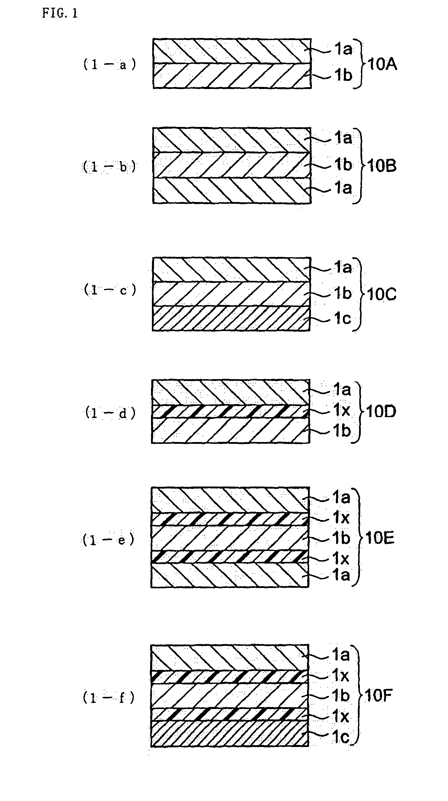
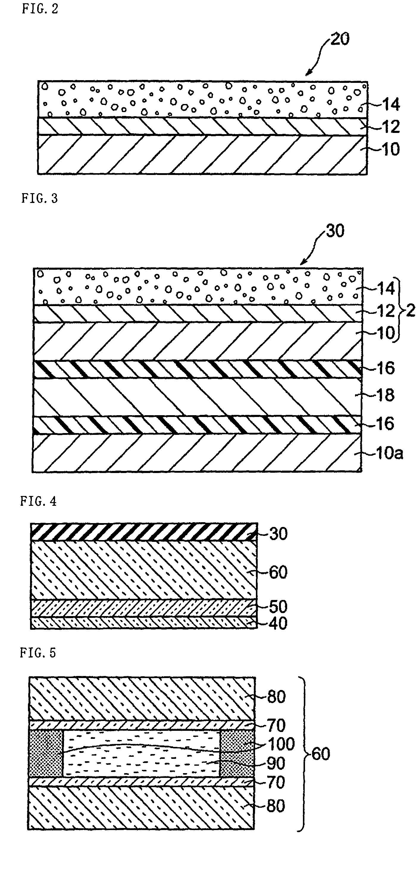
The present invention provides an antireflective film that has excellent antireflection performance, tenacity, and surface hardness. The film includes an antireflective layer and a base resin layer, with the base resin layer including layers a and b that have different flexural moduli. The difference in flexural modulus between the layers a and b is 0.2 GPa to 2.5 GPa. The antireflective layer includes a low-refractive-index layer with a refractive index of 1.40 or less. The film can be obtained by coextrusion. The invention also provides a polarizer plate and a display that includes the antireflective film.

Problems solved by technology

However, an antireflective film exhibiting excellent tenacity and surface hardness cannot be obtained by using the multilayer films disclosed in the above patent documents.

Method used


Image

  • Antireflective film, polarizer plate and display
  • Antireflective film, polarizer plate and display
  • Antireflective film, polarizer plate and display

Examples


example 1

(1-1) Production of Transparent Film (1A) Forming Base Resin Layer

[0167]PMMA was supplied to a hopper provided to a double-flight 50-mm single-screw extruder (ratio of screw effective length L to screw diameter D (L / D)=28) equipped with a leaf-disk polymer filter with a pore diameter of 10 μm. The molten resin was supplied to a multi-manifold die with a die lip surface roughness Ra of 0.1 μm at an extruder exit temperature of 260° C. and an extruder gear pump rotational speed of 12 rpm.

[0168]NB was supplied to a double-flight 50-mm single-screw extruder (L / D=30) equipped with a leaf-disk polymer filter with a pore diameter of 10 μm. The molten resin was supplied to a multi-manifold die with a die lip surface roughness Ra of 0.1 μm at an extruder exit temperature of 260° C. and an extruder gear pump rotational speed of 6 rpm.

[0169]The molten PMMA (layer a), NB (layer b), and EVA1 (adhesive layer=layer x) were discharged from the multi-manifold die at 260° C. and cast onto a chill rol...

example 2

[0177]A coextruded transparent film (1B) with a width of 600 mm and a thickness of 100 μm formed of layer a (20 μm)-layer x (4 μm)-layer b (52 μm)-layer x (4 μm)-layer a (20 μm) was obtained in the same manner as in Example 1 except for using PS as the resin a instead of PMMA. An antireflective film (2B) was produced in the same manner as in Example 1.

example 3

[0178]A coextruded transparent film (1C) with a width of 600 mm and a thickness of 100 μm formed of layer a (30 μm)-layer x (4 μm)-layer b (66 μm) was obtained in the same manner as in Example 1 instead of a five-layer transparent film formed of three types of layers. An antireflective film (2C) was produced in the same manner as in Example 1.


PUM

PropertyMeasurementUnit
flexural modulusaaaaaaaaaa

Abstract

The present invention provides an antireflective film including at least an antireflective layer and a base resin layer, the base resin layer including at least layers a and b respectively including a thermoplastic resin as a main component, the layer a having a flexural modulus higher than that of the layer b, and the layer a being closer to the antireflective layer than the layer b, a polarizer plate obtained by bonding the antireflective film to a polarizer, and a display including the polarizer plate. According to the present invention, an antireflective film in which an antireflective layer is stacked on a transparent resin substrate and exhibits excellent antireflective performance, tenacity, and surface hardness, a polarizer plate using the antireflective film, and a display including the polarizer plate are provided.

Description

TECHNICAL FIELD[0001]The present invention relates to an antireflective film exhibiting high tenacity and high surface hardness, a polarizer plate obtained by bonding the antireflective film to a polarizer, and a display including the polarizer plate.BACKGROUND ART[0002]A method has been widely known which produces a multilayer film by stacking resins to make the most of the properties of the respective resins.[0003]For example, JP-A-6-255053 discloses a forming thermoplastic resin sheet having at least two layers in which at least one layer is an amorphous polyolefin, and a formed product of the thermoplastic resin sheet. JP-A-6-255053 describes that the thermoplastic resin sheet exhibits excellent steam barrier properties and transparency, does not exhibit thermal adhesion to a die, and can be molded over a wide temperature range.[0004]JP-A-8-281882 discloses a polystyrene film formed of a laminate of a polystyrene layer / acrylonitrile-butadiene-styrene copolymer layer / polystyrene ...

Claims


Application Information

Patent Timeline
Patent Type & Authority Patents(United States)
IPC IPC(8): B32B7/02B32B27/36B32B27/32B32B27/30B32B23/08G02B1/11B32B7/022G02B1/111G02B1/14G02B5/30G02F1/1335
CPCB32B27/08G02B5/3033B32B7/02B32B27/28B32B27/30B32B27/302B32B27/308B32B27/32B32B27/36G02B1/111Y10T428/24942G02F1/133502G02F2201/38B32B2255/10B32B2255/26B32B2255/28B32B2264/102B32B2307/412B32B2307/418B32B2307/546B32B2457/20Y10T428/31884Y10T428/31797Y10T428/31935Y10T428/31888Y10T428/3188Y10T428/31786Y10T428/31913Y10T428/31891Y10T428/31928Y10T428/31938Y10T428/31909Y10T428/31855B32B7/022
Inventor TOYOSHIMA, TETSUYAARAKAWA, KOUHEI
Owner ZEON CORP
Learn More