
Microcomputer and functional evaluation chip

a microcomputer and functional evaluation technology, applied in the field of microcomputers and functional evaluation chips, can solve the problems of incorrect operation mode selection and low cost, and achieve the effect of low cost and small siz

Inactive Publication Date: 2011-02-15
DENSO CORP
View PDF19 Cites 5 Cited by
  • Summary
  • Abstract
  • Description
  • Claims
  • Application Information

AI Technical Summary

Benefits of technology

The present patent aims to provide a microcomputer that can operate in multiple modes and can be tested using an external circuit. The microcomputer includes a mode counter, mode decoder, clock input terminal, data terminal, serial-to-parallel conversion unit, and a switching means that switches to a state that a CPU is capable of accessing to the input data buffer when the mode signal represents a test mode. The microcomputer can be coupled with an ICE-adaptive chip that sets the microcomputer to an ICE mode so that a date is inputted to and outputted from the data terminal, the data for evaluating function of the microcomputer and for debugging software in the microcomputer. The functional evaluation chip can be configured to be a small size at a low cost.

Problems solved by technology

However, the technology disclosed in the patent document 1 has underlying problems described below.
(1) If noise is convoluted to a reset terminal at the timing at which power-on reset is canceled, there is a fear that an incorrect operating mode may be selected.
(2) If latched data holding an operating mode is affected by, for example, alpha rays or electromagnetic noise, an incorrect operating mode is kept held.

Method used


Image

  • Microcomputer and functional evaluation chip
  • Microcomputer and functional evaluation chip
  • Microcomputer and functional evaluation chip

Examples


first embodiment

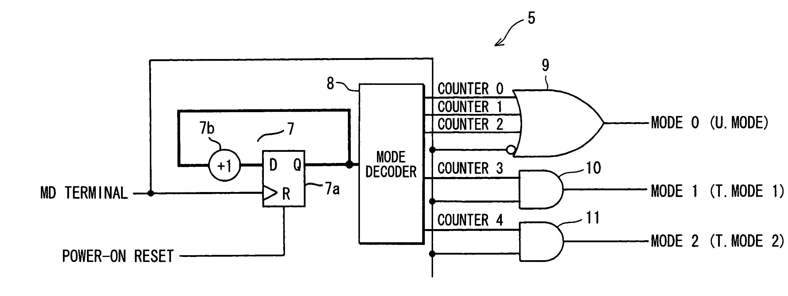
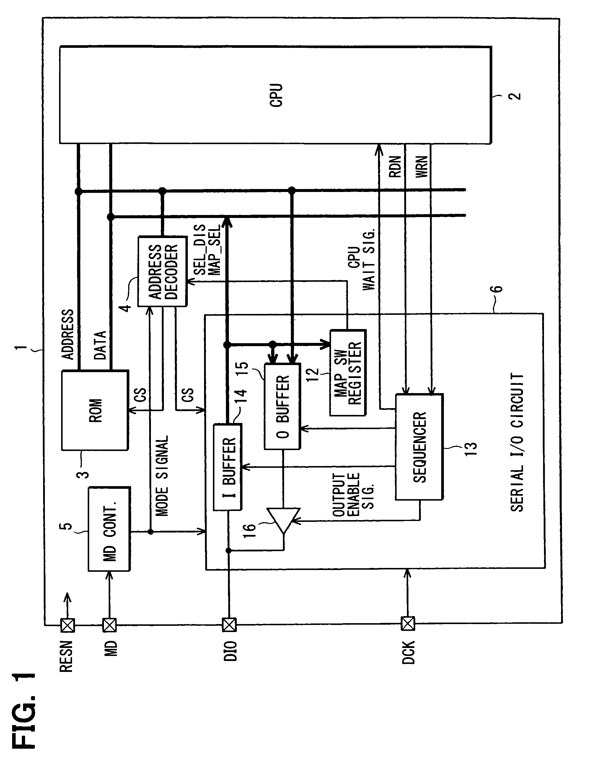
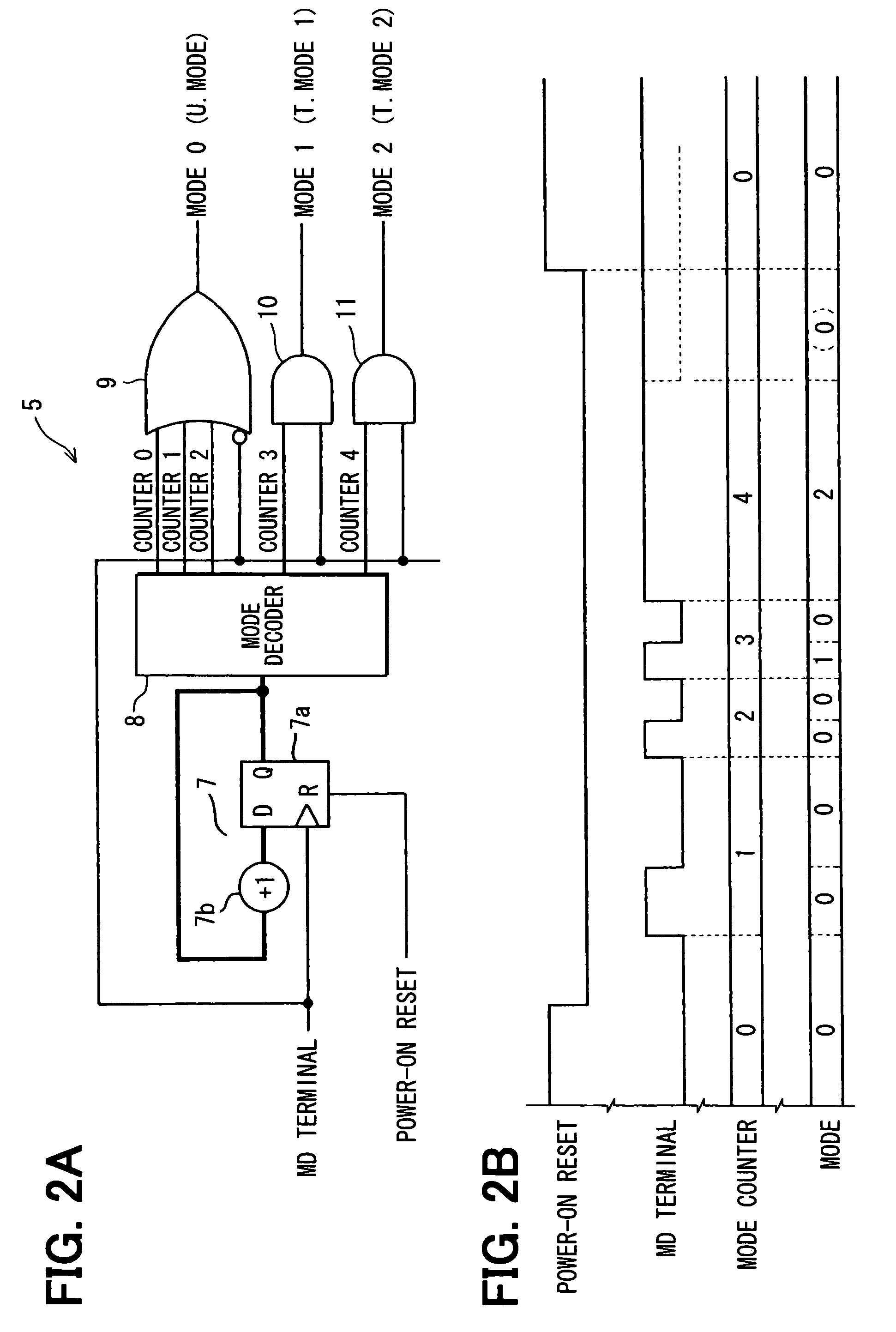
[0036]Referring to FIG. 1 to FIG. 5, the first embodiment will be described below. FIG. 1 shows part of the configuration of a microcomputer. A microcomputer 1 includes a CPU 2, a ROM (program memory) 3, an address decoder (switching means) 4, a mode control unit 5, and a serial input / output circuit (serial-to-parallel conversion unit) 6. The mode control unit 5 outputs a signal, with which an operating mode is designated for the microcomputer 1, according to the state of a change in an externally fed mode designation signal MD.

[0037]When the operating mode is a user mode (i.e., U MODE), the microcomputer 1 operates normally as a product according to a user program stored in the ROM 3. Moreover, when the operating mode is a test mode (i.e., T MODE), the microcomputer 1 fundamentally executes a test instruction that is externally inputted via the serial input / output circuit 6. When the operating mode is an ICE mode, the microcomputer 1 allows a functional unit to operate, the unit wh...

second embodiment

[0061]FIG. 6 to FIG. 9 show a second embodiment. The same reference numerals as those of the first embodiment will be assigned to identical components, and the description of the components will be omitted. Different components alone will be described below. In the second embodiment, an in-circuit emulator (ICE) is used to configure an evaluation chip (EVA chip) for use in development of the microcomputer 1. The microcomputer 1 that is a product is incorporated in the EVA chip.

[0062]FIG. 6 shows the configuration of a development system with the ICE and EVA chip centered on. An ICE 22 is connected to a personal computer (PC that is a host) 21, and an EVA chip 23 is connected to the ICE 22. The EVA chip 23 includes a standard chip (ICE-adaptive chip) 24 and the microcomputer 1. The ICE 22 communicates with the personal computer 21 via a host interface (I / F) 25 such as a universal serial bus (USB). In addition, the ICE 22 includes a monitor program 26 that allows execution of various ...

third embodiment

[0085]FIG. 10 to FIG. 12 show a third embodiment. The third embodiment also relates to the configuration of an EVA chip and is concerned with a case where an extensional configuration is adopted with the standard chip 24 and microcomputer chip 1 of the second embodiment used as fundamental components. An EVA chip 51 includes a standard chip (ICE-adaptive chip) 52 and two microcomputer chips 53A and 53B. The chips are, similarly to those of the second embodiment, interconnected through four kinds of terminals (MD terminals and RESN terminals are not shown). The standard chip 52 includes two data input / output terminals DIO1 and DIO2. The DIO1 terminal is connected to the DIO terminal of the microcomputer chip 53A, and the DI02 terminal is connected to the DIO terminal of the microcomputer chip 53B.

[0086]Moreover, as the standard chip of the second embodiment includes the peripheral functional unit 38, so the standard chip 52 includes functional units A and B (logic circuit units or th...


PUM


Abstract

A microcomputer for functioning according to operation modes includes; a mode counter that counts the number of times of level change in a signal applied to a mode setting terminal; a mode decoder that decodes output data of the mode counter to output a mode signal, which represents one operation mode; a clock input terminal; a data terminal through which serial data is inputted synchronously with a serial clock signal applied to the clock input terminal; a serial-to-parallel conversion unit that converts the serial data into parallel data and stores the parallel data in an input data buffer; and a switching means that switches to a state that a CPU can access to the input data buffer in a test mode. In the test mode, test instruction data is capable of being inputted from an external circuit.

Description

CROSS REFERENCE TO RELATED APPLICATIONS[0001]This application is based on Japanese Patent Applications No. 2007-173981 filed on Jul. 2, 2007, No. 2007-251687 filed on Sep. 27, 2007, and No. 2008-31819 filed on Feb. 13, 2008, the disclosures of which are incorporated herein by reference.FIELD OF THE INVENTION[0002]The present invention relates to a microcomputer and a functional evaluation chip.BACKGROUND OF THE INVENTION[0003]As for microcomputers, there is an incessant request for reduction in a chip size. A largest possible decrease in the number of external terminal is therefore an assignment to be achieved. For example, according to a technology disclosed in patent document 1 (JP-A-2001-273247), when an operating mode is externally designated for a microcomputer that operates with multiple operating modes switched, the operating mode is designated based on the level of a signal to be applied to a forcible reset terminal at the timing at which power-on reset is canceled. In this ...

Claims


Application Information

Patent Timeline
Patent Type & Authority Patents(United States)
IPC IPC(8): G06F11/00
CPCG06F11/26
Inventor ITO, NAOKIISHIHARA, HIDEAKIMATSUOKA, TOSHIHIKOMISAWA, KATSUTOYO
Owner DENSO CORP
Learn More