
Aberrometer provided with a visual acuity testing system

a technology of visual acuity and aberration, applied in the field of aberrometers and ophthalmologic instruments, can solve the problems of inability to achieve the inconvenient adjustment of aberrations, and inability to achieve best ratio between maximal and minimal aberration values, etc., to achieve the effect of improving the functional capabilities of ophthalmologic instruments, increasing the convenience of ophthalmologic instruments, and improving patient comfor

Inactive Publication Date: 2011-02-22
VISIONICA
View PDF12 Cites 12 Cited by
  • Summary
  • Abstract
  • Description
  • Claims
  • Application Information

AI Technical Summary

Benefits of technology

"The patent describes an invention that provides a more precise ophthalmologic instrument with a large number of functional capabilities. The invention includes an aberrometer that automatically measures the aberrations of the eye and determines their impact on subjective visual acuity. The instrument also has an alignment system and a method for compensated measurement of aberrations that allows for the simultaneous measurement of higher-order aberrations. The invention aims to improve the accuracy of measurements and enhance the conditions of use of the instrument. The technical effects of the invention include increased precision of the ophthalmologic instrument, automation of controls, simplification of the design, and improved alignment of the instrument. The invention also includes a method for compensated measurement of aberrations that allows for the simultaneous measurement of higher-order aberrations."

Problems solved by technology

The process is rather tedious and lengthy, especially in the case of complicated astigmatism (see E. I. Kovalevsky, Ophthalmology, Moscow, Medicine publishers, 1995, pp.
While measuring aberrations, an increased dynamic range, that is, the best ratio between the maximal and minimal aberration values may not be achieved with the use in the device of the Shack-Hartman's wavefront sensor because it does not allow measuring aberrations with large and small amplitudes equally well.
If the parameters of the sensor are selected so as to increase the range of measurement, small aberrations are measured with considerable errors.
Because both small and large aberrations occur in clinical practice, this factor is a serious disadvantage of aberrometers equipped with such sensors.
Yet when the light spot on the retina is small, the influence of phase and amplitude speckle modulation increases, which results in a lower precision of measurements.
Besides, when a probing beam of a considerable diameter is used, the conditions requiring a single-pass measurement are not met and certain aberrations self-compensate during the second pass of the beam.
On the contrary, its excessive smallness leads to the loss of precision.
The disadvantages of such system include their functional limitation because cylindrical instead of astigmatic wavefront is produced.
There are also their complicated mechanical controls.
A disadvantage of this astigmatism correcting device is that it may not be controlled automatically because its mechanical drive is too complicated, the rotation of the said lenses being mutually dependent (their turning angles are equal, while the axis of the instrument is adjusted by turning the whole device around its optical axis).
Because there is no test pattern projector in this prototype, the device is not suitable for testing visual acuity and for subjectively assessing the quality of and controlling the correction.
Another disadvantage of the instrument is the lack in it of a self-testing capability and of the automatic calibration of its mechanical and optical elements in order for the instrument to remain in a usable condition.
This is why the results of the use of control signals for estimating correction profiles become incorrect.
The need for operators' participation makes automation impossible.
Internal calibrating devices that include optical testing elements are hard to make and require additional beam-splitting plates or switchable optical elements.
The lack in the existing instrument of an adjustment system used for aligning the input pupil of the instrument with the pupil of the eye reduces the precision of measurements, the drawback becoming greater as the order of measured aberrations becomes higher and their magnitude increases.
The use of a computer makes the instrument and the adjustment procedure significantly more complicated.
The problem is the difficulty, for the operator, of finding the working area of the electronic system and determining the direction of misalignment.
The disadvantages of this device and adjustment method include the low precision of measurements because it depends on the forming of the slot images on the cornea and also the limitation of its use, when the light source is weak, by the visible part of the light spectrum which is inconvenient for the patient whose cornea is transparent so observation is possible only because of light scattering.
Besides, the design of the marks used in the prototype device does not allow the operator to explicitly determine the direction of misalignment.

Method used


Image

  • Aberrometer provided with a visual acuity testing system
  • Aberrometer provided with a visual acuity testing system
  • Aberrometer provided with a visual acuity testing system

Examples


Embodiment Construction

[0088]Below please find information confirming the viability of the group of inventions which are the substance of this application and their ability to function as described.

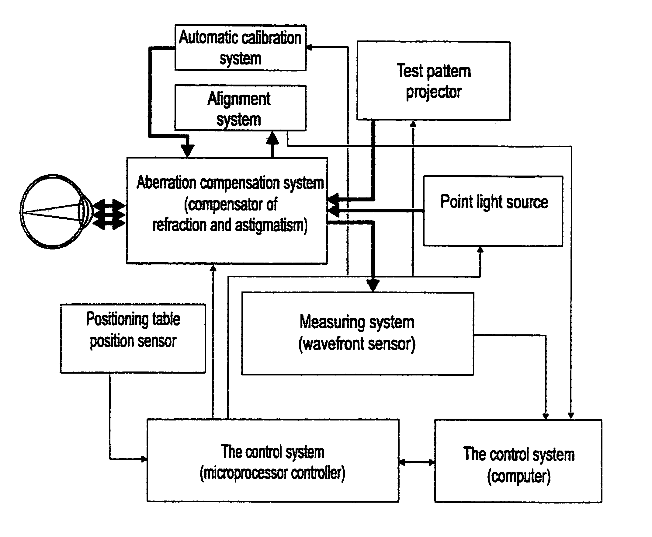
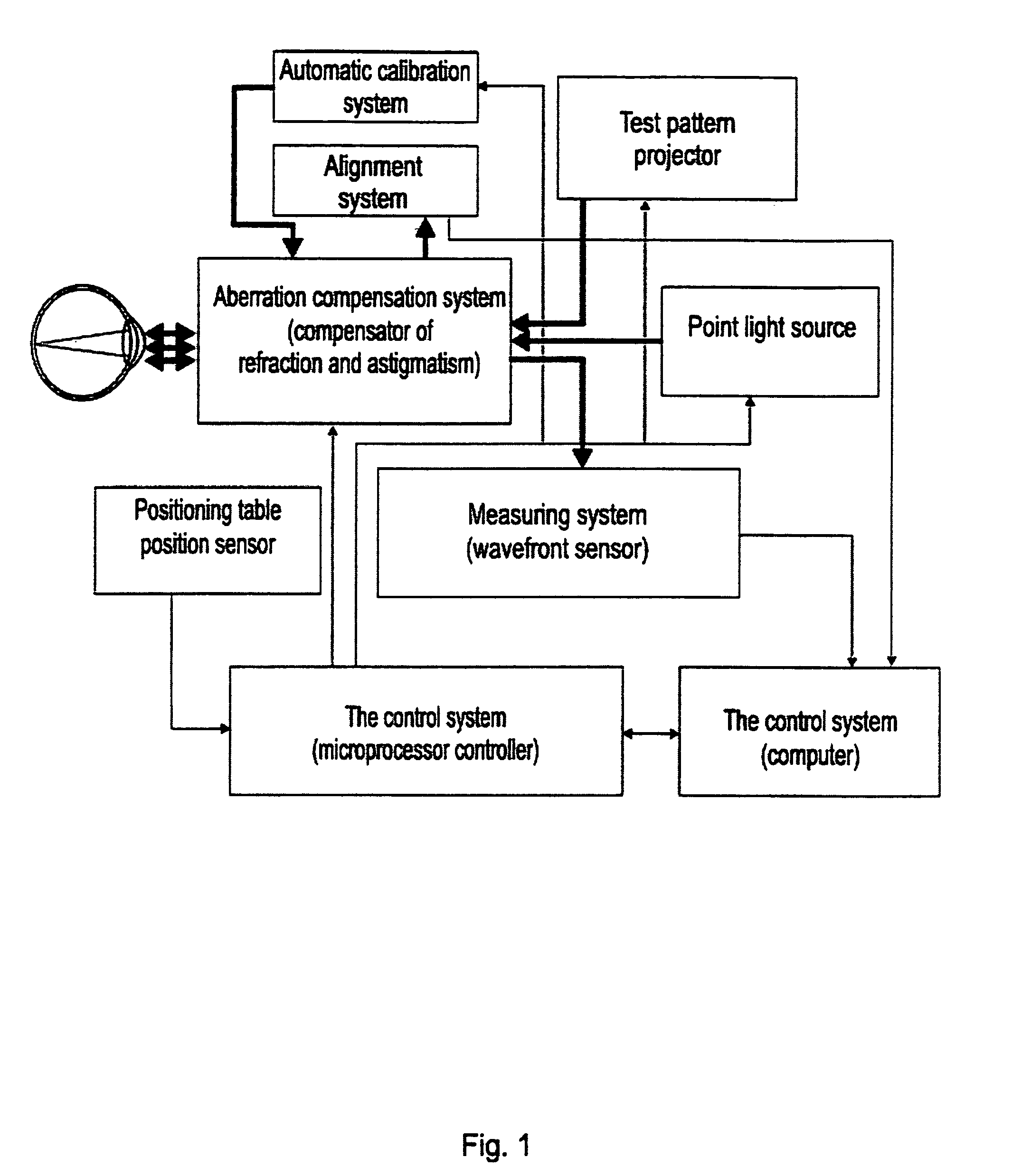
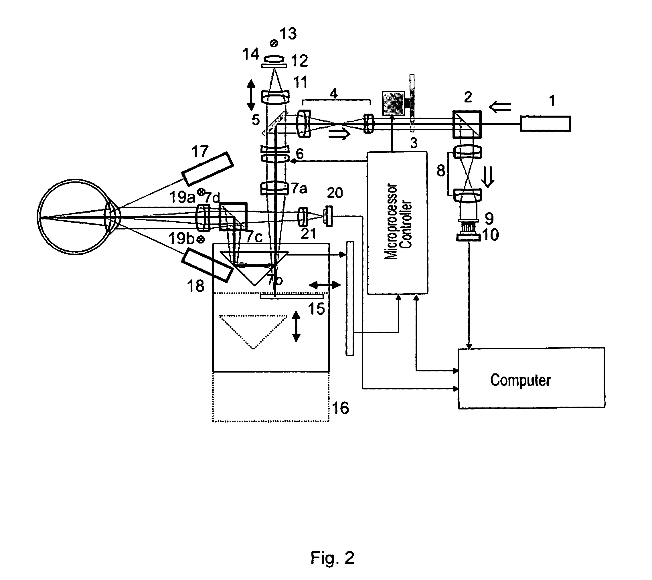
[0089]The aberrometer with a system for testing visual acuity comprises the following structural units (see FIGS. 1 and 3):[0090]1) a point light source[0091]2) a measuring system based on a wavefront sensor (of the Sack-Hartman type)[0092]3) a system compensating casual aberrations, comprising a refraction and astigmatism compensator and a higher-order aberrations compensator (see FIG. 3)[0093]4) an alignment system (a pointing camera)[0094]5) a projector of test patterns[0095]6) an automatic calibration and self-testing system[0096]7) a control system including a computer and a microprocessor controller

[0097]The ophthalmologic instrument intended for measuring the aberrations of the human eye and testing visual acuity, which is the substance of this application, is built on the basis of Shack-Hartman's wavefr...


PUM


Abstract

An aberrometer is provided for automatically measuring a human eye aberration, determining a subjective visual acuity associated with the selection of a best spherocylindrical correction, and investigating the influence of high orders aberrations on the visual acuity. The aberrometer includes a point light source which is projected on the eye retina, scattered back by the retina, and passes through the eye optical systems acquiring a phase modulation corresponding to the total eye optical aberration. The aberrometer also includes a wave front sensor whose output signal is transmitted to a device control system, an aberration compensation system which is disposed between the human eye and the wave front sensor and through which radiation coming out from the eye and projected on the eye retina passes, and a test picture projector which projects the test picture image on the eye retina through the aberration compensation system.

Description

[0001]This application is a U.S. National Phase Application under 35 USC 371 of International Application PCT / RU2005 / 000124 filed Mar. 22, 2005.BACKGROUND OF THE INVENTION[0002]1. Field of the Invention[0003]The group of inventions that is the substance hereof concerns the designs and adjustment of aberrometers, ophthalmologic instruments used in medical clinical practice for measuring aberrations of the human eye. The aberrometer presented herein as an invention is intended for automatically measuring aberrations of the human eye and determining subjective visual acuity while, simultaneously, selecting the best spherocylindrical correction in various accommodation statuses of the eye and, in the second modification of the instrument, for researching the influences of higher-order aberrations on subjective visual acuity and making forecasts as to the results of correcting vision with eyeglasses, individual contact lenses, intraocular lenses or laser ablation.[0004]The alignment syst...

Claims


Application Information

Patent Timeline
Patent Type & Authority Patents(United States)
IPC IPC(8): A61B3/10A61B3/028A61B3/032A61B3/103
CPCA61B3/032A61B3/1015
Inventor LARICHEV, ANDREY VICTOROVICHIROSHNIKOV, NIKITA GEORGIEVICHRESNYANSKY, ARTEM JURIEVICH
Owner VISIONICA
Learn More