
Regeneration apparatus and regeneration method for electroless plating

a technology of electroless plating and regeneration apparatus, which is applied in the direction of electrostatic separation, refining by electric/magnetic means, process and machine control, etc., can solve the problems of deterioration of film characteristic properties, abnormal precipitation, and plating rate drop

Inactive Publication Date: 2011-02-22
MURATA KK
View PDF13 Cites 1 Cited by
  • Summary
  • Abstract
  • Description
  • Claims
  • Application Information

AI Technical Summary

Benefits of technology

[0016]The present invention has been made in view of the circumstances as described above, and an object of the invention is to provide a regenerating apparatus and a regenerating method for an electroless plating solution by which the regenerating treatment of the electroless plating solution can be efficiently and automatically practiced.
[0026]According to the regenerating apparatus and the regenerating method for an electroless plating solution of the present invention, it becomes possible to carry out efficiently and automatically regenerating treatment of the electroless plating solution, so that calcium phosphite separated contains little amount of impurities, and hence, it is reusable as an industrial product and no industrial waste is produced.

Problems solved by technology

When electroless nickel plating is conducted by the use of the plating solution having such a composition as described above, phosphite produced as a result of oxidation of hypophosphite, sulfate of a reaction residue derived from nickel sulfate used for the nickel source, and further, a sodium salt or ammonium hydroxide being a reaction residue of sodium hydroxide or ammonium hydroxide used for pH adjustment are accumulated in the plating solution over time, resulting in decrease in plating rate, the appearance of abnormal precipitation, deterioration of film characteristic properties and the like.
In this respect, however, since 1995, dumping of waste at sea has been banned under the Convention on the Prevention of Marine Pollution by Dumping of Waste and other Matter, and punishment for dumping waste on land has become severe.
Concerning the removal of sodium phosphite or sodium sulfate accumulated in the course of electroless nickel plating operation, a variety of approaches has been made already; the fact is, however, that none of these approaches can reach industrial practical application.
According to the method, however, there are such disadvantages that effective components are removed from the plating solution together with the unnecessary components, and in addition, that the apparatus therefor becomes big and expensive.
However, the method involves technical and economical problems, so that the method has not yet been applied for practical use.
However, any of these involves many problems in view of practical use.
A large amount of a sulfate existing in an electroless plating solution accompanies not only extreme difficulty in separation from the plating solution, but also increase in a solubility of calcium phosphite, so that it becomes a significant disability for separating the phosphite.
However, since there is no contrivance for automation as to the drawn rate of the plating solution for separating the phosphite, it is required to calculate an amount of the plating solution to be drawn and an amount of the calcium hydroxide or calcium carbonate to be added in each case based on the plating throughput to be processed, and thus, there is a problem of poor multiusability.

Method used


Image

  • Regeneration apparatus and regeneration method for electroless plating
  • Regeneration apparatus and regeneration method for electroless plating
  • Regeneration apparatus and regeneration method for electroless plating

Examples


Embodiment Construction

[0033]In the following, the best mode for practicing the present invention will be described by referring to the accompanying drawings.

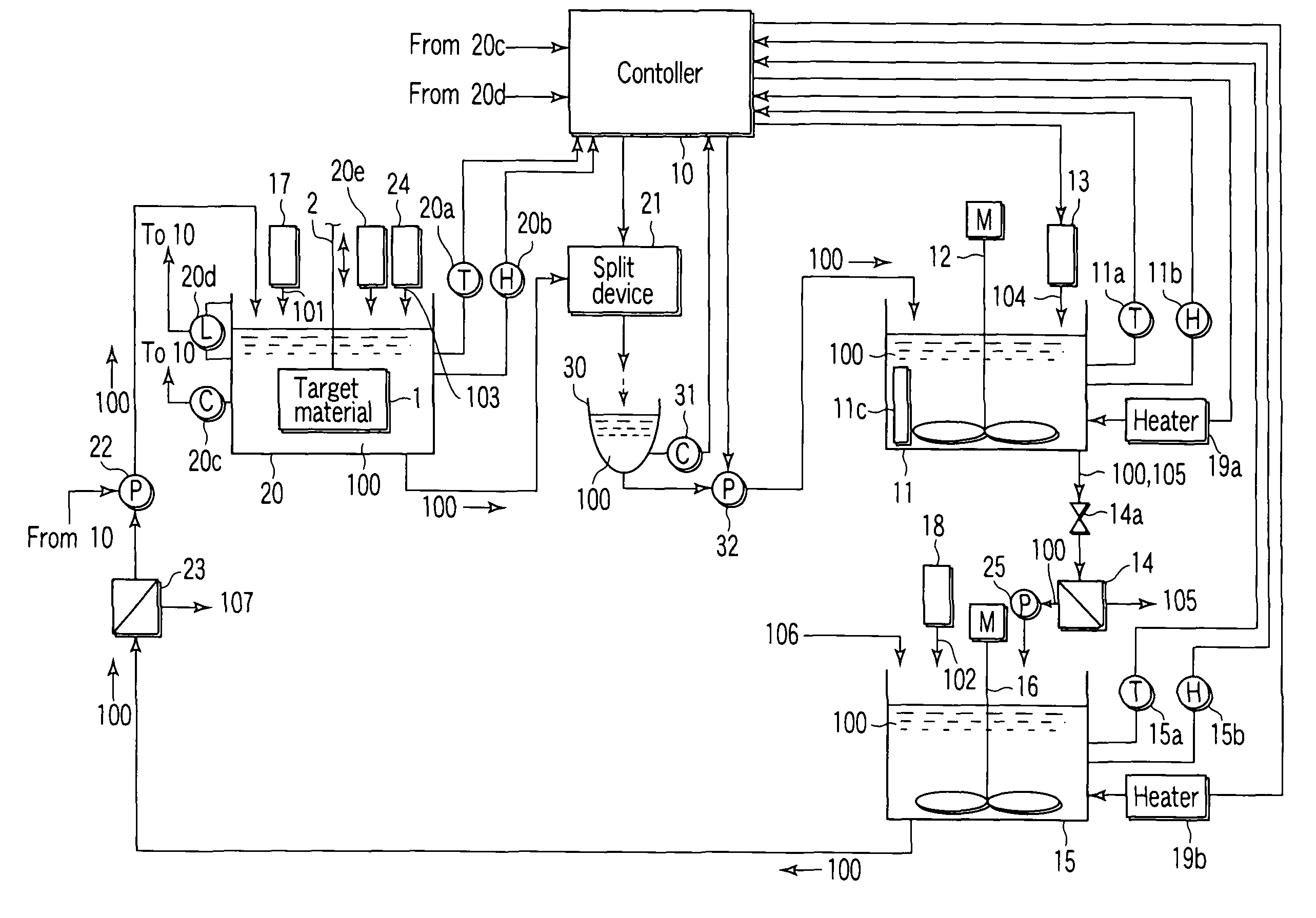
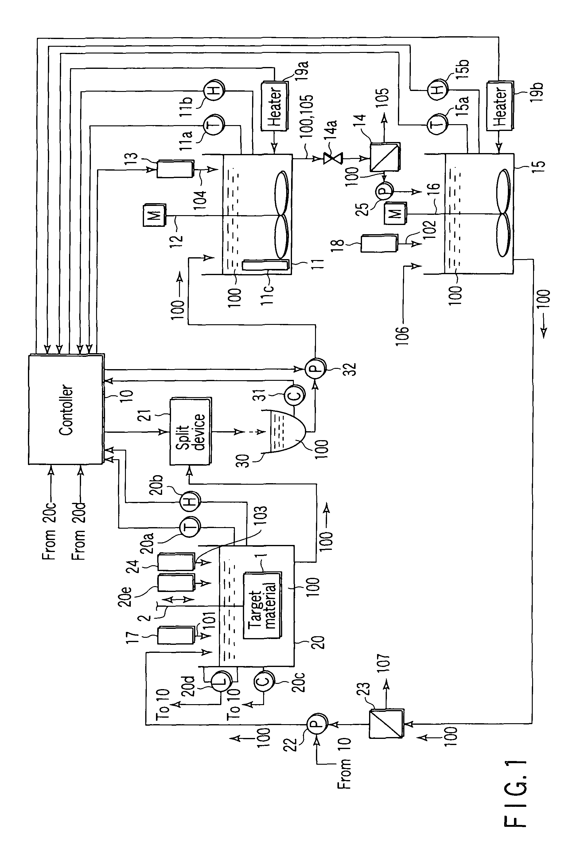
[0034]FIG. 1 is a schematic diagram showing a constitutional example of a regenerating apparatus to which a regenerating method for an electroless plating solution according to an embodiment of the present invention is applied.

[0035]More specifically, the regenerating apparatus is provided with a plating tank 20 having a built-in heating device; and the plating tank 20 accumulates a plating solution 100 wherein nickel hypophosphite is used as a nickel source 101, and further at least one or more members selected from nickel hypophosphate, sodium hypophosphate, and hypophosphorous acid are used as reducing agents, the plating tank 20 further serving to contain a target material 1 therein to apply nickel plating to the target material 1.

[0036]As facilities associated with the plating tank 20, the regenerating apparatus is provided with a replenishment ...


PUM

PropertyMeasurementUnit
concentrationaaaaaaaaaa
concentration measurementaaaaaaaaaa

Abstract

A regeneration apparatus for an electroless plating solution includes a sensor for measuring the formation rate of phosphorous acid formed in a plating tank in response to a plating treatment, a split device for taking out a plating solution in the plating tank to transfer the plating solution to a first processing tank, a sensor for measuring the concentration of the phosphorous acid contained in the plating solution taken out, an addition device for supplying calcium carbonate or calcium hydroxide, an amount of which is required for producing a calcium phosphite from the phosphorous acid contained in the plating solution, to the first processing tank, a separation device for separating and removing the calcium phosphite produced in the first processing tank from the plating solution, and a return pump for transferring the plating solution from which the calcium phosphite has been separated and removed to the plating tank.

Description

CROSS-REFERENCE TO RELATED APPLICATIONS[0001]This application is based upon and claims the benefit of priority from prior Japanese Patent Application No. 2005-203266, filed Jul. 12, 2005, the entire contents of which are incorporated herein by reference.BACKGROUND OF THE INVENTION[0002]1. Field of the Invention[0003]The present invention relates generally to an electroless plating technology in which a material to be plated is immersed in a plating solution to apply nickel plating, and particularly to an apparatus and a method for regenerating an electroless plating solution, which has been used in a plating treatment, in order to reuse it.[0004]2. Description of the Related Art[0005]Heretofore, in an electroless plating method in which, for example, hypophosphite is used as a reducing agent for applying nickel plating, a material prepared by combining nickel sulfate (nickel source) with sodium hypophosphite (reducing agent) is usually applied. When electroless nickel plating is con...

Claims


Application Information

Patent Timeline
Patent Type & Authority Patents(United States)
IPC IPC(8): B01J49/00
CPCG05D21/02C23C18/1617C23C18/1669C23C18/1683
Inventor TAKAGAMI, HIDENORIKAWAKAMI, HIROSHIKATO, KAZUHIKO
Owner MURATA KK
Learn More