Laser for coherent LIDAR

Inactive Publication Date: 2011-02-22
OCEANIT LAB
View PDF18 Cites 95 Cited by
  • Summary
  • Abstract
  • Description
  • Claims
  • Application Information

AI Technical Summary

Benefits of technology

[0011]The present invention is methods for achieving optimum coaxial lidar configuration using optical fibers. Optical fibers are used with mirrors or lenses to create light paths that can achieve an optimum lidar configuration while employing fewer components than that of prior art for a more simplified, lightweight, and less expensive system to produce. The lidar components, including the laser source and the light detector un

Problems solved by technology

Naturally, accuracy using this method depended somewhat on the reactions and eyesight of the observer and could be complicated by such issues as wind and local topography.
This produces problems in overlap of the transmitting beam and the receiving field of view for certain ranges.
For full overlap of the trans

Method used


Image

  • Laser for coherent LIDAR
  • Laser for coherent LIDAR
  • Laser for coherent LIDAR

Examples


embodiment 73

[0037]FIG. 4 shows an embodiment 73 where a receiver optical fiber 75 is inverted and a receiver optical configuration utilizes a parabolic or spherical mirror 77 to reflect received light 79 into a receiver optical fiber end 81 which guides light through the optical fiber 75 and to a detector 83. Transmitted light 85 travels through a transmitter optical fiber 87 and comes from a laser source 89. The transmitted light 85 passes through a collimating lens 91 in the center of the apparatus 73. This configuration provides a more compact size than the system of FIG. 3, while maintaining the advantage of better isolation of transmit and receive optical paths.

[0038]FIG. 5 shows an embodiment 93 where both a transmitter optical fiber 95 from a laser 97 and receiving optical fiber 99 to a detector 101 are inverted. The embodiment 93 of FIG. 5 also employs independent parabolic or spherical mirrors 103, 105 to achieve desired optical paths. Transmitted light 107 exits the laser-coupled opti...

embodiment 143

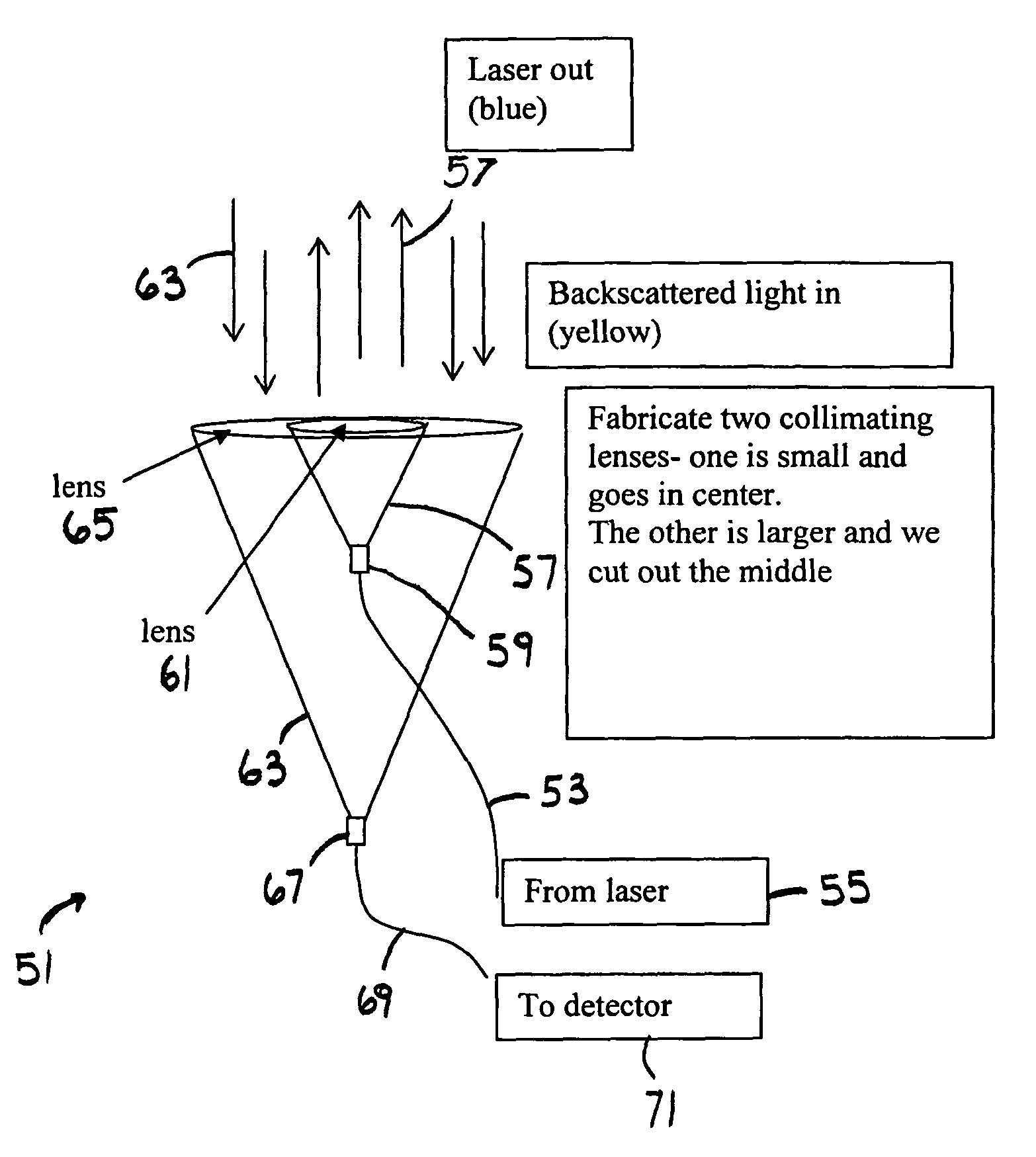
[0040]FIG. 8 shows an embodiment 143 where a receiver fiber 145 is upright and receives light 147 from a secondary mirror 153 located behind a transmitter fiber 151 and receives light at fiber end 146 before a detector 148. The secondary mirror 153 receives light from the parabolic (or spherical) primary mirror 149 below the receiver optical fiber 145. Transmitted light 155 leaves a laser 157, travels through a transmitter fiber 151 and through a fiber end 159. The transmitted light 155 passes through a collimating lens 161 that is small and goes in the center of the apparatus 143. The configuration in FIG. 8 provides a compact co-axial configuration.

embodiment 163

[0041]FIG. 9 shows an embodiment 163 where a transmitting optical fiber 165 is inverted off angle to a parabolic (or spherical) mirror 167. Transmitted light 169 is generated by a laser 171, travels through the transmitting optical fiber 165 and exits a fiber end 173 and then reflects off of the mirror 167 and is collimated by the collimating lens 175. Received light 177 is reflected off a second mirror 179 and up to an underside 181 of the first mirror 167. The underside 181 of the first mirror 167 then reflects the received light 177 into a received fiber end 183, through a receiver optical fiber 185 and into a detector 187.


PUM


Abstract

A method for achieving optimum coaxial lidar configuration using optical fibers. Optical fibers are used with mirrors or lenses to create light paths that can achieve an optimum lidar configuration while employing fewer components than that of prior art for a more simplified, lightweight, and less expensive system to produce. The lidar components, including the laser source and the light detector unit, may be placed in a separate housing. A separate housing eliminates unnecessary weight in the optical telescope assembly, makes scanning of the system easier, and enables a better omni-directional cloud height indicator.

Description

[0001]This application claims the benefit of U.S. Provisional Application No. 61 / 068,927, filed Mar. 11, 2008, which is hereby incorporated by reference in its entirety.TECHNICAL FIELD OF THE INVENTION[0002]The present invention relates to lidar.BACKGROUND OF THE INVENTION[0003]The very earliest cloud height measurements utilized ceiling balloons of various weights and lifts, inflated with helium. The time interval between the release of the balloon and its entry into the base of the clouds was recorded. The point of entry for layers aloft was considered as midway between the point at which the balloon began to fade and that when it completely disappeared. With surface based clouds, the time interval ended when the balloon completely disappeared. During the day, red balloons were used with thin clouds and black balloons were used with thicker clouds and at night, a battery-powered light was attached. Naturally, accuracy using this method depended somewhat on the reactions and eyesig...

Claims


Application Information

Patent Timeline
IPC IPC(8): G01C3/08
CPCG01S17/95G01S7/4818Y02A90/10
Inventor SULLIVAN, CHRISTOPHER J.
Owner OCEANIT LAB
Why Eureka
Try Eureka