Electrochromic compound, electrochromic composition and display device

a technology of electrochromic composition and compound, applied in the field of electrochromic compound, electrochromic composition and display device, can solve the problems of low light utilization efficiency, low contrast ratio, and difficult development of display device offering all of these characteristics, and achieve the effect of improving the memory performance of an electrochromic compound

Inactive Publication Date: 2011-02-22
RICOH KK
View PDF28 Cites 7 Cited by
  • Summary
  • Abstract
  • Description
  • Claims
  • Application Information

AI Technical Summary

Benefits of technology

[0010]The present invention has been accomplished in view of the above-mentioned conditions and problems of the conventional art, and aims at improving memory performance of an electrochromic compound and a reflective display device using the compound.

Problems solved by technology

In terms of its display characteristics, in particular, it is required that electronic paper has as excellent white reflectivity and contrast ratio as paper does, and the development of a display device offering all of these characteristics is far from easy.
The media, however, have the following problems: low light-utilizing efficiency due to the use of a polarizing plate; being incapable of displaying colors other than dark white; and low contrast ratio because of incapability of displaying black color.
In such a device, however, it is practically difficult to completely reverse the white particles and the black particles so that it is hard to simultaneously satisfy high white reflectivity and high contrast ratio.
However, it is clear that an excellent image quality cannot be obtained by forming a color filter on a display medium having low white reflectivity and low contrast ratio.
These devices cannot solve the above-mentioned problems in principle, and cannot simultaneously fulfill high white reflectivity and high contrast ratio.
However, the electrochromic compounds illustrated in the two publications form colors such as blue and green, but cannot form three primary colors, i.e., yellow, magenta and cyan, which are necessary for producing a full color display.
Although these electrochromic compounds can form the three primary colors, they have no memory effect, so that when voltage-applying is stopped, these compounds lose their colors in about one second.
If a display device has no memory performance, it needs continuous power supply for producing colors.
Thus since the greater the memory performance, the lower the power consumption can be, so that enhancement of memory performance is important problem.

Method used


Image

  • Electrochromic compound, electrochromic composition and display device
  • Electrochromic compound, electrochromic composition and display device
  • Electrochromic compound, electrochromic composition and display device

Examples


example 1

[0070]The electrochromic compound having the structure represented by the Formula (7) shown below was obtained according to the following synthetic process.

[0071]Bis(4-formylphenyl)phenylamine was reduced in ethanol with 2 equivalents of sodium borohydride to obtain bis(4-hydroxymethylphenyl)phenylamine. The obtained bis(4-hydroxymethylphenyl)phenylamine was reacted with equimolar p-toluenesulfonylchloride to replace a hydroxyl group at one end with a toluenesulfonyl group, and then the resultant compound was reacted with trimethylphosphite to yield a triphenylamine phosphate derivative having the structure represented by the Formula (6), as an intermediate compound.

[0072]

[0073]The compound of Formula (6) was reacted with terephthalic acid monomethyl chloride in a THF solvent, and then the phosphonic acid ester was hydrolyzed with a diluted hydrochloric acid, whereby the compound having the structure represented by the Formula (7) was yielded.

[0074]

example 2

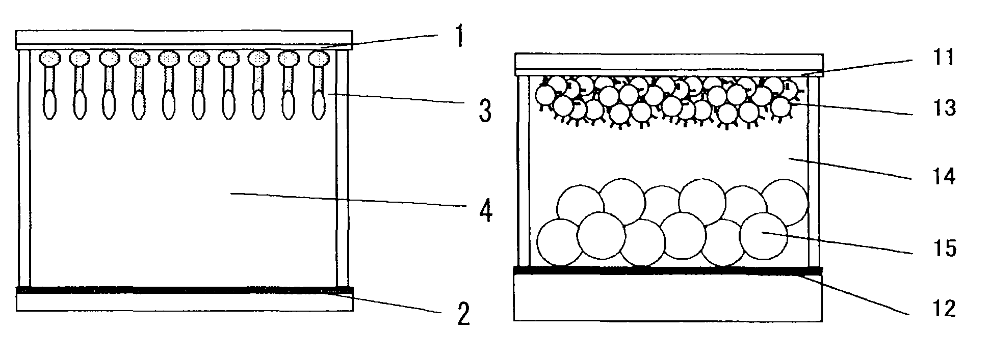
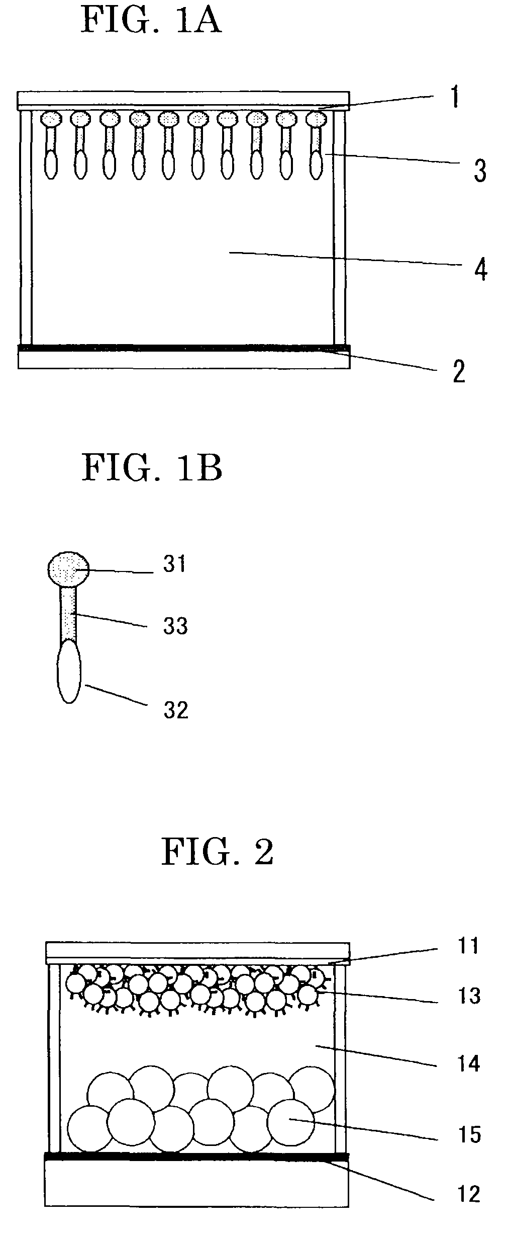
[0075]0.2 M of the compound of Formula (7) obtained in Example 1 was dissolved in ethanol, and to the resultant solution, a glass base plate covered wholly with a tin oxide transparent electrode film was immersed for 24 hours, to adsorb the compound of Formula (7) to the surface of the electrode film, whereby a display electrode was prepared.

[0076]Meanwhile, the glass base plate covered wholly with a tin oxide transparent electrode film was placed in a 0.2% by mass aqueous solution of hexachloroplatinic acid and a constant electric flow of 1 mA / cm2 was applied for 30 seconds to deposit a platinum film on the surface, whereby a counter electrode was prepared.

[0077]The display electrode and the counter electrode were attached together by the intermediary of a 100 μm thick spacer to obtain a cell. Into the cell, an electrolyte solution prepared by dissolving 0.2 M of tetrabutylammonium chloride in dimethylformamide was poured, whereby a display device was produced.

[0078]An anode and a ...

example 3

[0082]The compound of Formula (6) obtained in Example 1 was reacted with 4,4-biphenylcarboxylic acid monoethylchloride in a THF solvent, and then the resultant phosphonate was hydrolyzed with a diluted hydrochloric acid, whereby the compound having the structure represented by Formula (9) was yielded.

[0083]

[0084]An display device was produced in the same manner as in Example 2 except that the electrochromic compound was replaced lo with the compound of Formula (9). An anode and a cathode were respectively connected to the display electrode and the counter electrode, followed by impression of a voltage of 3 V for one second. The display device produced yellow, and the coloring state continued for about 100 seconds after the impression of the voltage.


PUM

PropertyMeasurementUnit
particle diameteraaaaaaaaaa
thickaaaaaaaaaa
voltageaaaaaaaaaa

Abstract

An electrochromic compound having in the molecule at least an adsorbable group, a redox chromophore and a spacer portion, and represented by the following General Formula (1):wherein A represents the adsorbable group, C represents the redox chromophore, and X represents the spacer portion represented by the following formula;wherein R1 and R3 each represent an aliphatic hydrocarbon group or an aromatic derivative group, R2 represents a hydrogen atom or a monovalent group.

Description

BACKGROUND OF THE INVENTION[0001]1. Field of the Invention[0002]The present invention relates to a display device, specifically to a structure of display device using a color forming material capable of repeatedly changing its color by a redox reaction; a reflective display; and an electronic paper.[0003]2. Description of the Related Art[0004]Recently, much research effort has been made to electronic paper as an electronic medium that is expected to displace paper. In contrast to conventional displays including CRTs and liquid crystal displays (LCDs), electronic paper requires the following characteristics: being a reflective display device; high white reflectivity and contrast ratio; high definition display; memory effect; low-voltage drive capability; slimness; lightness; and inexpensiveness, etc. In terms of its display characteristics, in particular, it is required that electronic paper has as excellent white reflectivity and contrast ratio as paper does, and the development of ...

Claims


Application Information

Patent Timeline
Patent Type & Authority Patents(United States)
IPC IPC(8): G02F1/153G02F1/15G02B26/00G02F1/1516
CPCC09K9/02C09K2211/1007C09K2211/1014G02F1/15G02F1/1516
Inventor HIRANO, SHIGENOBUSHIBUYA, TAKESHIKONDO, HIROSHINAKAMURA, YUKIABE, YUKIKOYASHIRO, TOHRU
Owner RICOH KK
Why Eureka
Try Eureka