

Ink jet recording element
- Summary
- Abstract
- Description
- Claims
- Application Information
AI Technical Summary
Benefits of technology
Problems solved by technology
Method used
Image

Examples
example 1
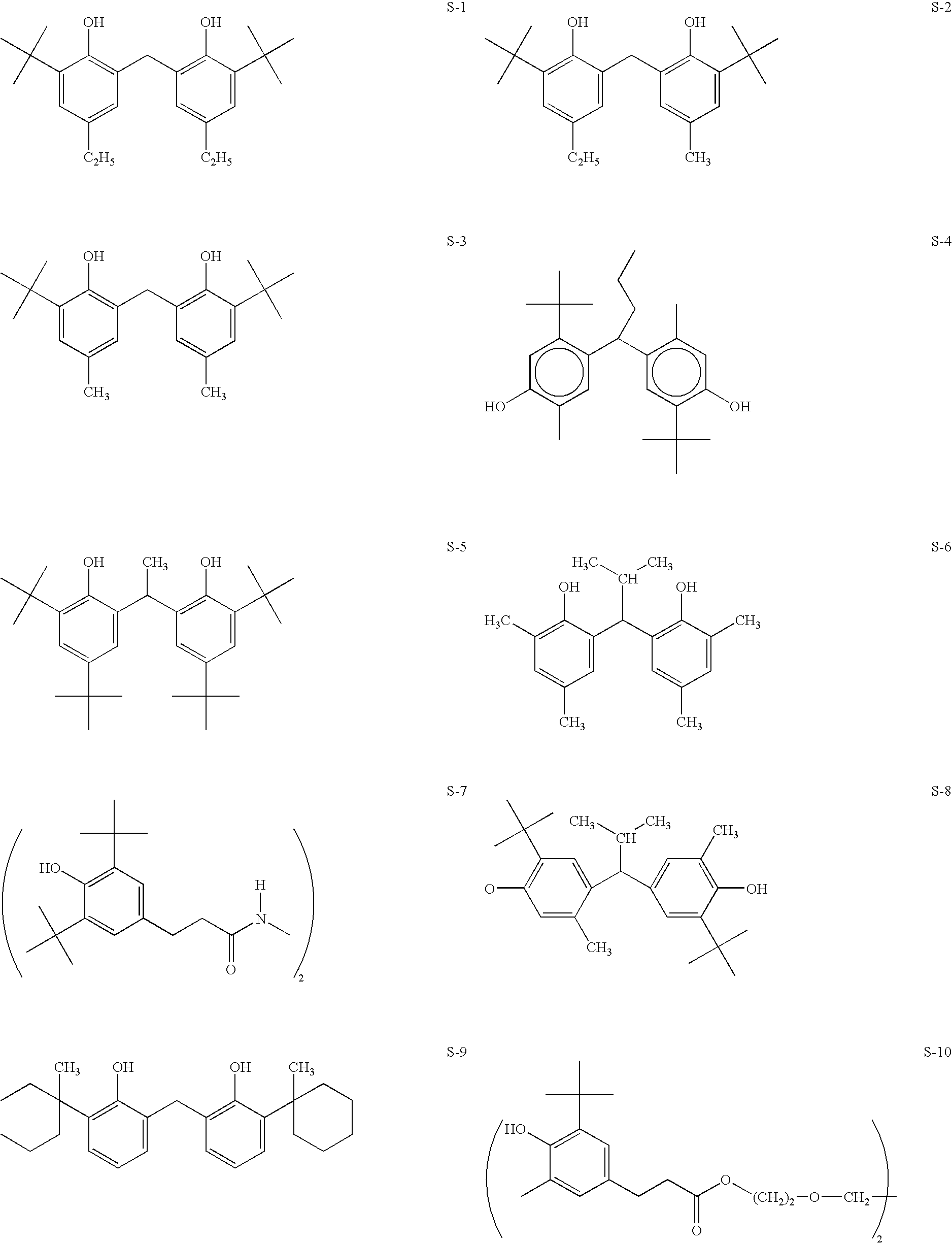
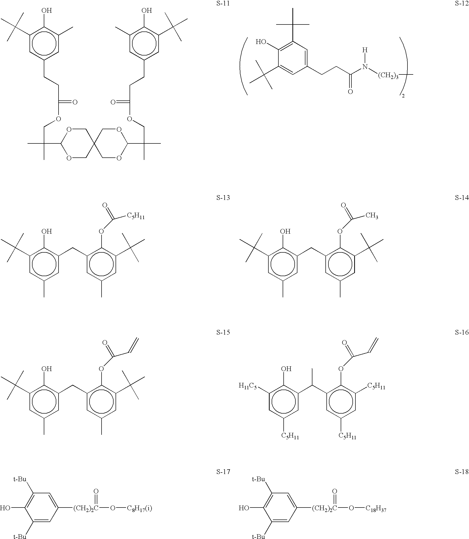
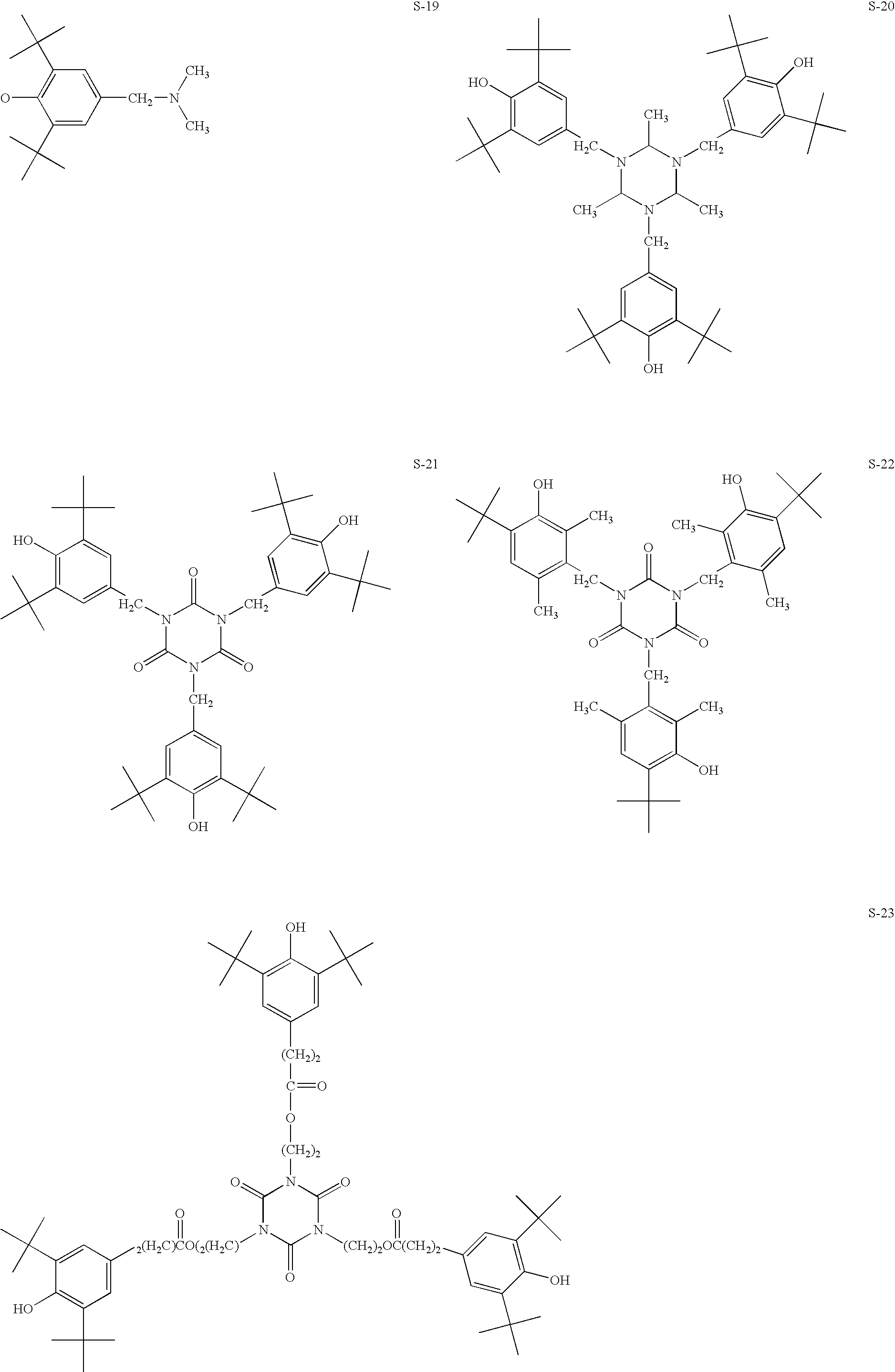
Stabilizer Particles in Base Layer
Comparative Element C-1 (No Stabilizer Particles in the Base Layer)
[0061]Base layer coating solution 4 was coated onto a photographic base paper and dried at about 90° C. to give a dry thickness of about 25 μm or a dry coating weight of about 27 g / m2.
[0062]Image receiving layer coating solution 1 was coated on the top of the base layer and dried at 90° C. to give a dry thickness of about 8 μm or a dry coating weight of about 8.6 g / m2.
Element 1 (Invention)
[0063]Element 1 was prepared the same as Comparative Element 1 except that the base layer coating solution 3 was used.
Element 2 (Invention)
[0064]Element 3 was prepared the same as Comparative Element 1 except that the base layer coating solution 1 was used.
Printing and Ambient Light Fading Test
[0065]The above elements were printed using a Kodak PPM 200® printer using color cartridges number 195-1730. The image consisted of adjacent patches of cyan, magenta, yellow, black, green, red and blue patches...
example 2
Stabilizer Particles in Image-Receiving Layer
Comparative Element C-2 (No Stabilizer Particles in Image-Receiving Layer)
[0068]Element C-2 was prepared the same as Element C-1 except that the imaging receiving layer coating solution 2 was used.
Element 3 (Invention)
[0069]Element 3 was prepared the same as Element 1 except that the image receiving layer coating solution 3 was used.
Element 4 (Invention)
[0070]Element 4 was prepared the same as Element 1 except that the image receiving layer coating solution 4 was used.
Gloss
[0071]The above recording elements were measured for 60° specular gloss using a Gardener® Gloss Meter.
[0072]The above elements were then printed and tested as in Example 1. The following results were obtained:
[0073]
TABLE 2Magenta DensityMagenta DensityElementGloss1Gloss2Loss (%)1Loss (%)2C-2305264.658.13416117.225.3438621422.41Before calendering2After calendering at 0.42 × 10⁶ kg / m2 (600 psi) and 52° C.
[0074]The above results show that the elements of the invention had ...
example 3
Stabilizer Particles in Base Layer and Image-Receiving Layer
Element 5 (Invention)
[0078]Element 5 was prepared the same as Element 3 except that the base layer coating solution 1 was used.
Element 6 (Invention)
[0079]Element 6 was prepared the same as Element 4 except that the base coating solution 2 was used.
[0080]The above elements were subjected to the accelerated ozone test as in Example 2. The following results were obtained:
[0081]
TABLE 4Magenta Density Loss (%)Cyan Density Loss (%)Element5 days7 days5 days7 days51536286122325
[0082]The above results show that the elements of the invention had good resistance to ozone fade.
PUM
| Property | Measurement | Unit |
|---|---|---|
| Percent by mass | aaaaa | aaaaa |
| Percent by mass | aaaaa | aaaaa |
| Percent by mass | aaaaa | aaaaa |
Abstract
Description
Claims
Application Information