
Gasoline sulfur reduction catalyst for fluid catalytic cracking process

a sulfur reduction and catalyst technology, applied in the direction of physical/chemical process catalysts, hydrocarbon oil treatment products, chemistry apparatus and processes, etc., can solve the problems of high equipment and operational cost, difficult to remove thiophenic compounds, and high cost of approach, so as to reduce the sulfur content

Inactive Publication Date: 2011-03-08
WR GRACE & CO
View PDF36 Cites 3 Cited by
  • Summary
  • Abstract
  • Description
  • Claims
  • Application Information

AI Technical Summary

Benefits of technology

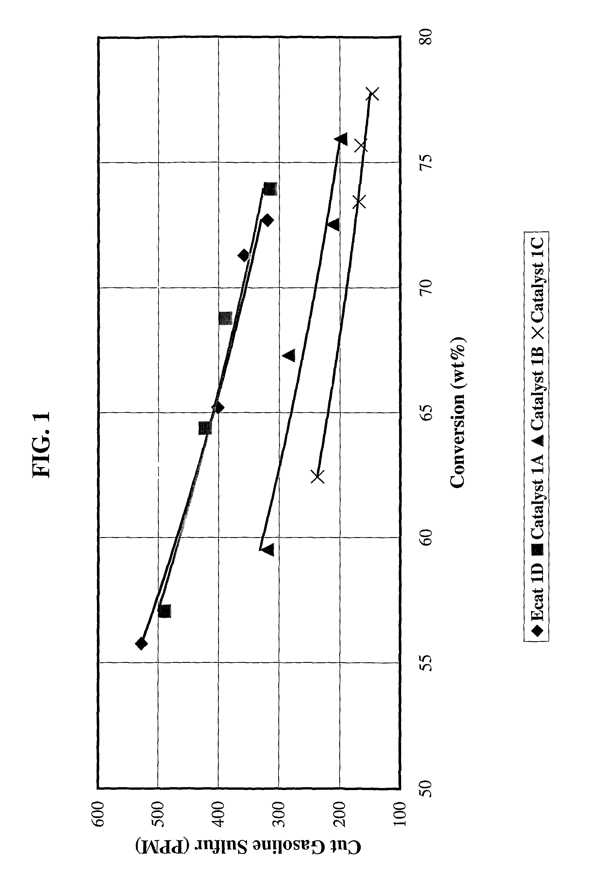
[0021]FIG. 7 illustrates the effect of the invention versus catalysts that do not contain both, e.g., zinc, and yttrium on cut gasoline sulfur reduction as further described in Example 3.
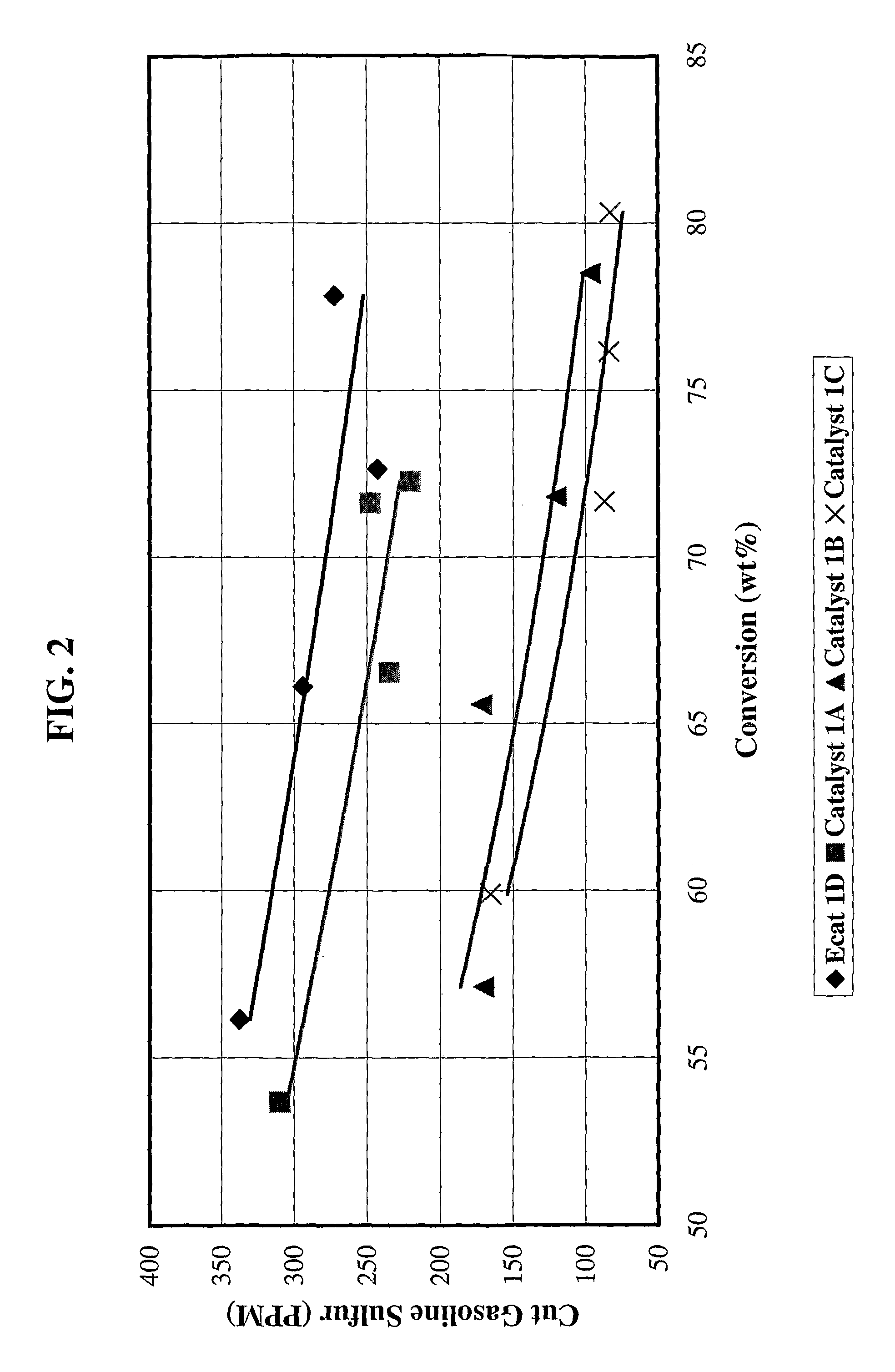
[0022]FIG. 8 illustrates the effect of the invention versus catalysts that do not contain both, e.g., zinc, and yttrium on LCO sulfur reduction as further described in Example 3.
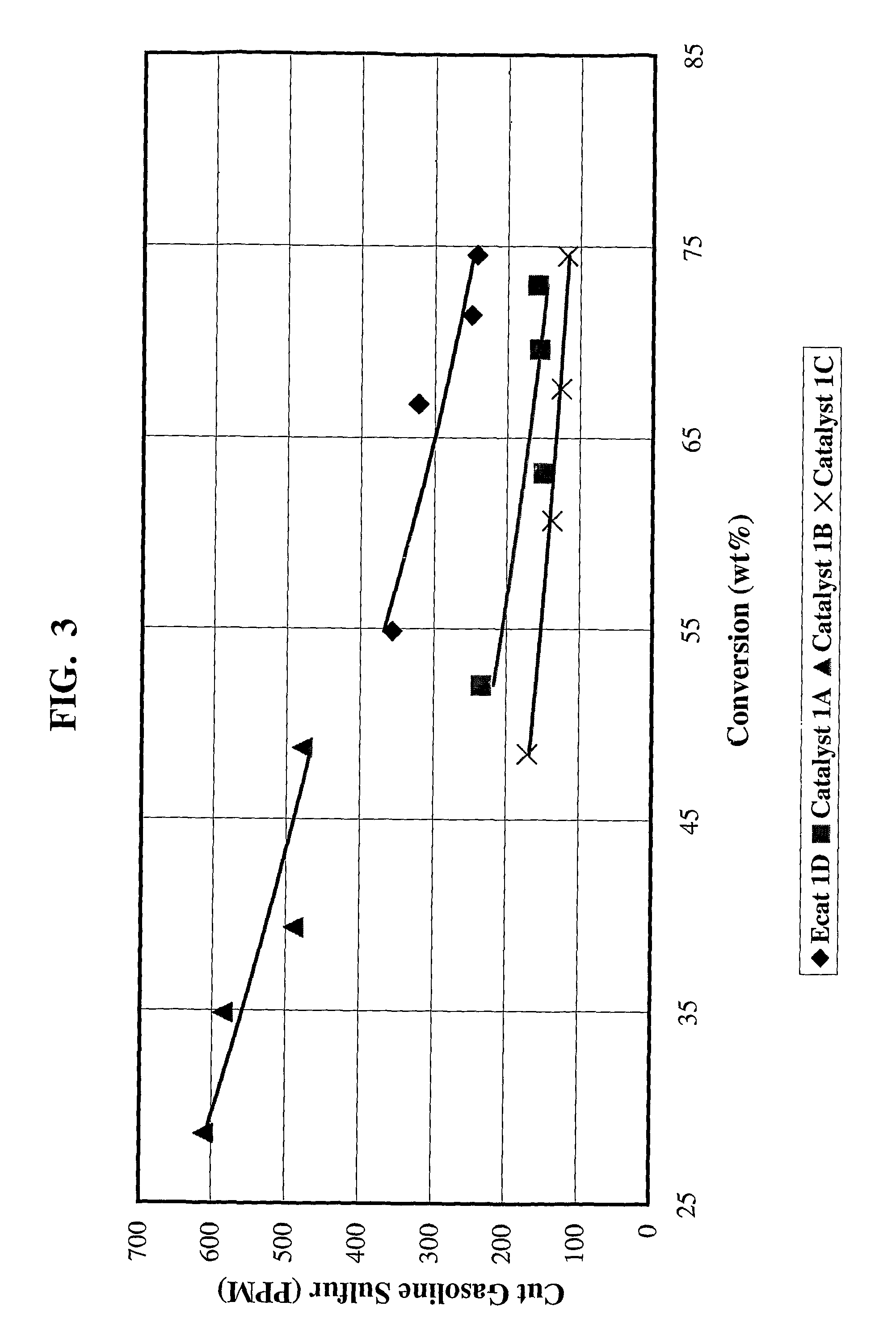
[0023]FIG. 9 illustrates the hydrocarbon conversion (wt %) and cut gasoline sulfur reduction performance of the invention (Catalyst 4C and 4D of Example 4) versus a base equilibrium catalyst (E-cat 1D) and other catalysts (Catalyst 4A & 4B).
[0024]FIG. 10 illustrates the hydrocarbon conversion (wt %) and LCO sulfur reduction performance of the invention (Catalyst 4C and 4D of Example 4) versus a base equilibrium catalyst (E-cat 1D) and other catalysts (Catalyst 4A & 4B).SUMMARY OF THE INVENTION
[0025]The present invention is an improved cracking catalyst composition comprising zeolite, yttrium, and at least one element selected from the group consisting of zinc, magnesium, and manganese, wherein the yttrium and the element are present as cations. The catalyst composition preferably comprises zinc as the aforementioned element in amounts of about 0.1% to about 14%. The catalyst also preferably comprises about 0.1% to about 12% by weight yttrium. The element and yttrium are generally present in the composition as cations that have been exchanged onto the zeolite. The zeolite is preferably zeolite Y. The invention can further contain rare earth, e.g., when rare earth exchanged Y zeolite is employed. The composition is particularly suited for use in a fluidized catalytic cracking process (FCC). Accordingly preferred embodiments of the invention comprise fluidizable particles having an average particle size in the range of about 20 to about 100 microns, and further comprise matrix and optionally binder, e.g., clay and alumina.
[0026]The invention also provides for a new method of reducing the sulfur content of a catalytically cracked petroleum fraction, which comprises catalytically cracking a petroleum feed fraction containing organosulfur compounds at elevated temperature in the presence of a cracking catalyst comprising zeolite, yttrium, and at least one element selected from the group consisting of zinc, magnesium, and manganese, wherein the yttrium and element are present as cations.

Problems solved by technology

Indeed, fluidized catalytic cracking (FCC) processes produce a large amount of the refinery gasoline blending pool in the United States.
The thiophenic compounds have been found to be most difficult to remove.
While highly effective, this approach tends to be expensive in terms of the capital cost of the equipment as well as operationally since hydrogen consumption is high.
Again, while effective, this solution has the drawback that valuable product octane may be lost when the high octane olefinic components become saturated.
Although this system has the advantages of causing sulfur reduction in the cracking process, it is generally believed that use of greater than about 10 weight percent of the described additives in the catalyst composition does not provide a benefit (e.g. high sulfur removal while retaining the selectivity of other products) proportional to the level of the additive.
A FCC catalyst constantly goes through alternative reduction and oxidation cycles under hydrothermal conditions in a FCC process and therefore avoiding these cycles is not usually possible.
These shortcomings have limited the use of these types of catalysts.

Method used


Image

  • Gasoline sulfur reduction catalyst for fluid catalytic cracking process
  • Gasoline sulfur reduction catalyst for fluid catalytic cracking process
  • Gasoline sulfur reduction catalyst for fluid catalytic cracking process

Examples


example 1

[0079]Catalyst 1A: 4203 grams (1350 g on a dry basis) of RE-USY with 8.2% RE2O3, 0.15% Na2O was mixed with 547 g of a ZnCl2 solution containing 29.6% Zinc for 10 minutes. Then, 1761 g (405 g on a dry basis) aluminum chlorohydrol and 2991 g (2542 g on a dry basis) clay were added in the above slurry and mixed for about 10 minutes. The mixture was milled in a Drais mill to reduce particle size and spray dried in a Bowen spray dryer. The spray dried particles were calcined for 1 hour at 1100° F. (593° C.). The physical and chemical properties of the finished fresh catalyst are listed on Table 1.

[0080]Catalyst 1B: 3663 grams (1200 g on a dry basis) of RE-USY with 8.2% RE2O3, 0.15% Na2O was mixed with 486 g of a ZnCl2 solution containing 29.6% Zinc and 667 g of a RECl3 solution containing 19.6% rare earth for 10 minutes. Then, 1565 g (360 g on a dry basis) aluminum chlorohydrol and 2447 g (2080 g on a dry basis) clay were added in the above slurry and mixed for about 10 minutes. The mixt...

example 2

[0103]5000 g Na—Y zeolite was exchanged with ammonium sulfate to lower the Na2O content to ˜4%. Then, 4.62% yttrium was exchanged on the washed Na—Y zeolite by slurrying one part of the zeolite and 10 parts of YCl3 solution that contains 0.051 part of yttrium at pH 5 for 20 minutes followed by filtering and rinsing with 30 parts of deionized water. The exchange zeolite was dried overnight at 120° C. followed by calcination of 2 hours at 1150° F. (621° C.). The calcined zeolite was exchanged again with ammonium sulfate to lower the Na2O content to ˜0.69%.

[0104]A starting base catalyst was made by mixing 3767 grams (1500 g on a dry basis) of the yttrium exchanged zeolite above with 400 g deionized water, 2391 g (550 g on a dry basis) aluminum chlorohydrol and 3471 g (2950 g on a dry basis) clay for about 10 minutes. The mixture was milled in a Drais mill to reduce particle size and spray dried in a Bowen spray dryer. The finished catalysts were calcined and exchanged using ammonium su...

example 3

[0116]The same starting base catalyst in the Example 2 was impregnated with 1.23% yttrium using YCl3 solution to incipient wetness followed by calcinations of 1 hour at 1100° F. (593° C.). The finished catalyst is named Catalyst 3A. Three additional catalysts were made by incipient wetness impregnation of Catalyst 3A using ZnCl2 solution.[0117]Catalyst 3B: 10 g of catalyst 3A were impregnated to a Zn level of 2.39% followed by a calcination of 1 hour at 100° F. (593° C.).[0118]Catalyst 3C: 110 g of catalyst 3A were impregnated to a Zn level of 3.16% followed by a calcination of 1 hour at 1100° F. (593° C.).[0119]Catalyst 3D: 10 g of catalyst 3A were impregnated to a Zn level of 3.97% followed by a calcination of 1 hour at 1100° F. (593° C.).

[0120]All four catalysts were deactivated 16 hours at 1420° F. (771° C.) with 100% steam. The physical and chemical properties of the four catalysts after the deactivation are listed in Table 9.

[0121]All four catalysts were tested in a MAT agains...


PUM

PropertyMeasurementUnit
particle sizeaaaaaaaaaa
sizeaaaaaaaaaa
particle sizesaaaaaaaaaa

Abstract

The invention is a composition that is suitable for reducing sulfur species from products produced by petroleum refining processes, especially gasoline products produced by fluidized catalytic cracking (FCC) processes. The composition comprises zeolite, yttrium, and at least one element selected from the group consisting of zinc, magnesium and manganese, wherein the yttrium and element are present as cations. The yttrium and zinc are preferably present as cations that have been exchanged onto the zeolite. The zeolite is preferably a zeolite Y.

Description

FIELD OF THE INVENTION[0001]The present invention is directed to an improved catalyst composition useful in fluid catalytic cracking processes. The present catalyst composition is capable of reducing sulfur compounds normally found as part of the gasoline fraction streams of such processes. The present invention accordingly provides product streams of light and heavy gasoline fractions with substantially lower amounts of sulfur-containing compounds, and an improved catalytic cracking process when the invention is used as a catalyst in such processes.BACKGROUND OF THE INVENTION[0002]Catalytic cracking is a petroleum refining process that is applied commercially on a very large scale. Indeed, fluidized catalytic cracking (FCC) processes produce a large amount of the refinery gasoline blending pool in the United States. In the process, heavy hydrocarbon feedstocks are converted into lighter products by reactions taking place at elevated temperatures in the presence of a catalyst, with ...

Claims


Application Information

Patent Timeline
Patent Type & Authority Patents(United States)
IPC IPC(8): B01J29/08B01J29/16
CPCB01J29/061B01J29/088B01J29/166C10G11/05B01J35/023B01J2229/18C10G2400/02C10G2300/202C10G2300/4093C10G2300/70B01J2229/42B01J29/06B01J29/08
Inventor HU, RUIZHONGWORMSBECHER, RICHARD FRANKLIN
Owner WR GRACE & CO
Learn More