
High isolation wavelength division devices

a wavelength division and high isolation technology, applied in the field of optical communication, can solve the problems of inconvenient design, high cost, and inability to achieve b>200/b>, and achieve the effect of high isolation, reduced cost, and reduced cos

Inactive Publication Date: 2011-03-22
ALLIAN FIBER OPTIC PROD INC
View PDF2 Cites 19 Cited by
  • Summary
  • Abstract
  • Description
  • Claims
  • Application Information

AI Technical Summary

Benefits of technology

One of the objects, features, advantages of the present invention is to provide a mechanism of high isolation for the R-channel from the T-channel channel such that the errors or residuals to the R-channel are minimized. The devices so designed are amenable to small footprint, broad operating wavelength range, enhanced impact performance, lower cost, and easier manufacturing process.

Problems solved by technology

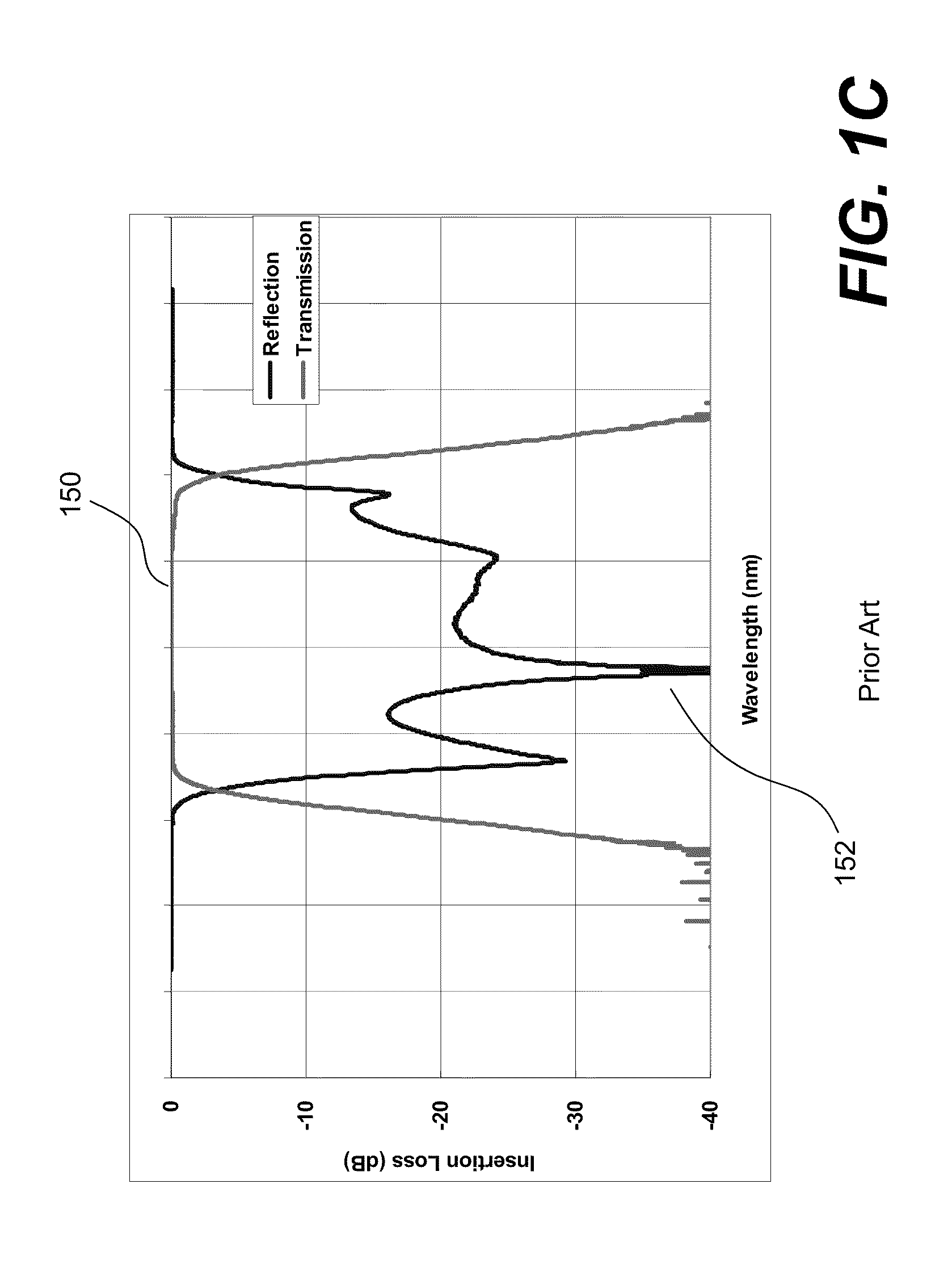
However, the optical filters by the state-of-art TFF deposition technique can only achieve 97.5% to 99% transmission for the T-channel signal.
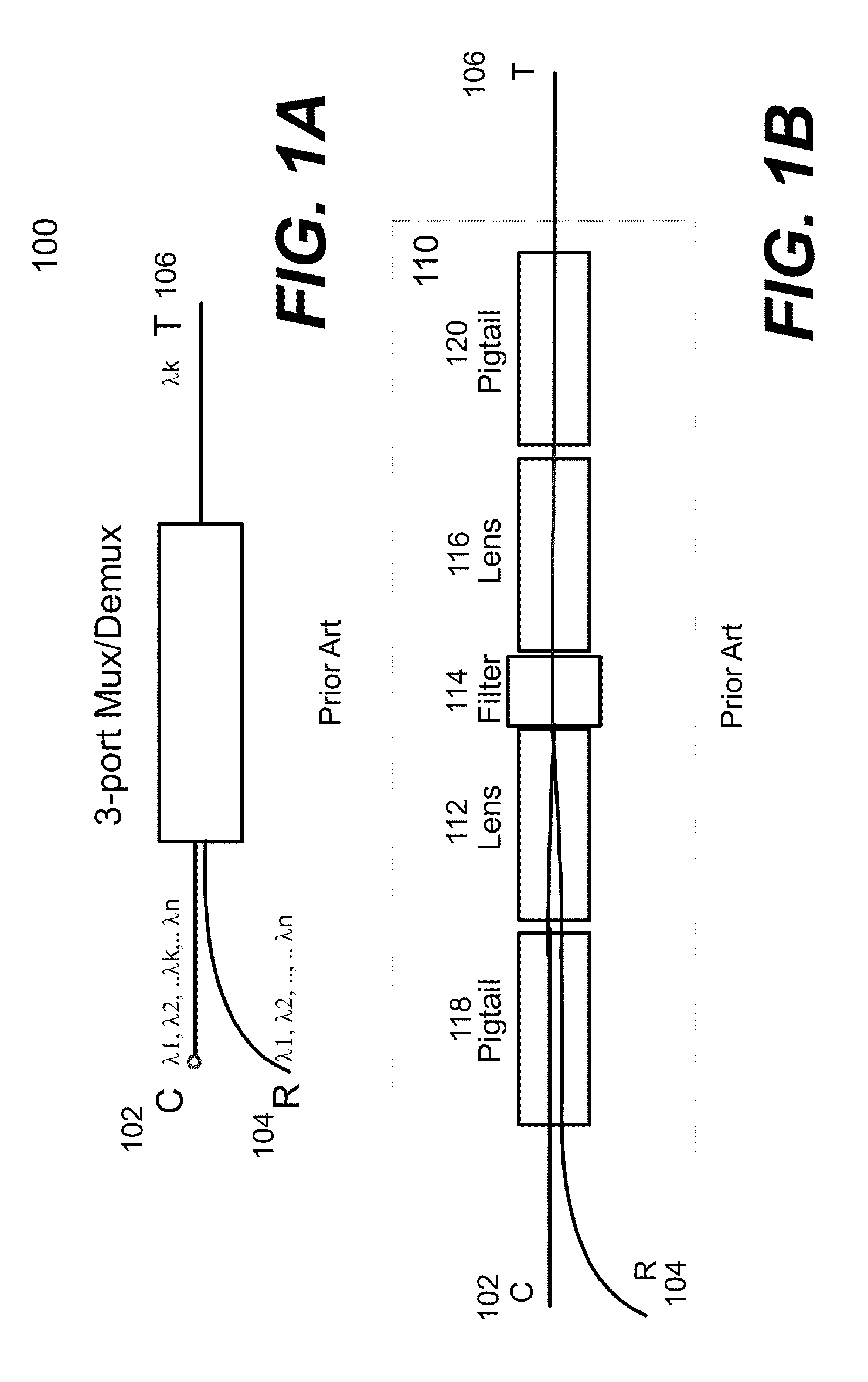
As a result, the residual of the T-channel signal would interfere with the R-channel signal, especially when a new signal is added into the transmission fiber that is using the same T-channel optical carrier signal, leading to complexity and difficulty when processing the R-channel signal. FIG. 1C shows a typical filter spectrum for both R-channel and T-channel.
Evidently, the design 200 is not desirable because of the high cost and bulky size
Although this approach increases the R-channel isolation, this approach demands stringent assembling tolerance and technical challenge.
In addition, the high isolation device build in such way suffers high cost and bulky size.
However, the performance is not as desirable as the free-space approach shown in FIG. 3.

Method used


Image

  • High isolation wavelength division devices
  • High isolation wavelength division devices
  • High isolation wavelength division devices

Examples


Embodiment Construction

The present invention pertains to new designs of optical devices particularly useful for adding or dropping a selected wavelength or a group of wavelengths as well as multiplexing a plurality of signals into a multiplexed signal or demultiplexing a multiplexed signal into several signals. One of the important features in the present invention is to provide a mechanism for high isolation of signals in one optical path from signals in another optical path. In particular, high isolation of the R-channel from the T-channel is provided in devices designed in accordance with the present invention to minimize errors or residuals of the T-channel in the R-channel signals.

According to one aspect of the present invention, an optical filter and a reflecting element are used. Depending on implementation, the reflecting element may be another optical filter, a prism and a mirror. The reflecting element is provided to direct a reflected light beam from the optical filter back to the optical filte...


PUM


Abstract

Techniques for designing optical devices with high reflection isolation are disclosed. According to one aspect of the devices, an optical filter and a reflecting element are used. Depending on implementation, the reflecting element may be another optical filter, a prism and a mirror. The reflecting element is provided to direct a reflected light beam from the optical filter back to the optical filter for additional filtering, wherein the reflected light is a filtered signal that is presumably carrying residuals of unwanted signals (e.g., a transmitted signal of the optical filter). With a proper placement of the reflecting element with respect to the optical filter, the reflected light beam can be redirected back to the optical filter for a predefined number of times so that the errors or residuals in the reflected light beam are much reduced, if not completely removed.

Description

BACKGROUND OF THE INVENTION1. Field of the InventionThe invention is generally related to the area of optical communications. In particular, the present invention is related to optical wavelength multiplexing or add / drop devices with high reflection channel isolation and the method for making the same in compact size.2. The Background of Related ArtThe future communication networks demand ever increasing bandwidths and flexibility to different communication protocols. Fiber optic networks are becoming increasingly popular for data transmission due to their high speed and high capacity capabilities. Wavelength division multiplexing (WDM) is an exemplary technology that puts data from different sources together on an optical fiber with each signal carried at the same time on its own separate light wavelength. Using the WDM system, up to 80 (and theoretically more) separate wavelengths or channels of data can be multiplexed into a light stream transmitted on a single optical fiber. To ...

Claims


Application Information

Patent Timeline
Patent Type & Authority Patents(United States)
IPC IPC(8): H04J14/02G02B27/14
CPCG02B3/0087G02B6/29365G02B27/1006G02B27/14G02B27/145G02B6/29367
Inventor WANG, DAOYILI, YAO
Owner ALLIAN FIBER OPTIC PROD INC
Learn More