Coaxially arranged, off-axis optical system for a sighting device or aiming device

a technology of optical system and aiming mark, which is applied in the direction of surveying, navigation, weapons, etc., can solve the problems of system-dependent image errors, aiming errors, and not all of the rays proceeding from the aiming mark will be imaged at infinity, so as to achieve good flattening of the image field and high optical imaging quality of the aiming mark

Inactive Publication Date: 2011-03-29
NOBLEX E OPTICS GMBH
View PDF11 Cites 7 Cited by
  • Summary
  • Abstract
  • Description
  • Claims
  • Application Information

AI Technical Summary

Benefits of technology

[0024]It is an object of the invention to provide a possibility for constructing an optical system in such a way that the typical disadvantage with respect to the tightness of a sighting device in an open-type construction is overcome and a good flattening of the image field is achieved in addition to the high optical imaging quality of the aiming mark.

Problems solved by technology

However, the disadvantage in using only one spherical surface is that not all of the rays proceeding from the aiming mark will be imaged at infinity.
This image error is caused by the spherical aberration of a spherically shaped lens surface.
As a result, the system-dependent image errors are also increased.
In particular, it is disadvantageous when the pupil of the eye is not on the optical axis formed by the sighting optics, but rather is shifted toward the edge within the sighting window.
In connection with the off-axis view through the sight, this results in an aiming error, referred to as a parallax error, caused by the different distances of the observation object and the image of the aiming mark.
This error can also not be prevented by adjustments because the coincidence of the image plane and object plane on the optical axis is already produced.
However, it is possible for this parallax error to be increased even further by insufficient adjustment of the position of the aiming mark.
However, producing optical components of this kind with the required quality by conventional lens technologies is very uneconomical so that it is necessary to resort to injection-molded plastics.
Under robust and rugged use, however, lenses made from plastic, as opposed to glass, have disadvantages such as lower resistance to scratching and poor resistance to solvents and cleaning agents.
Also, it is particularly disadvantageous that the functionally important splitter layer is external and, therefore, with intensive use over a longer period of time, is highly vulnerable mechanically to the cleaning steps by themselves.
A considerable disadvantage consists in that the very good correction state achieved by a paraboloid only applies to a punctiform aiming mark which is positioned exactly on the optical axis.

Method used


Image

  • Coaxially arranged, off-axis optical system for a sighting device or aiming device
  • Coaxially arranged, off-axis optical system for a sighting device or aiming device
  • Coaxially arranged, off-axis optical system for a sighting device or aiming device

Examples


Embodiment Construction

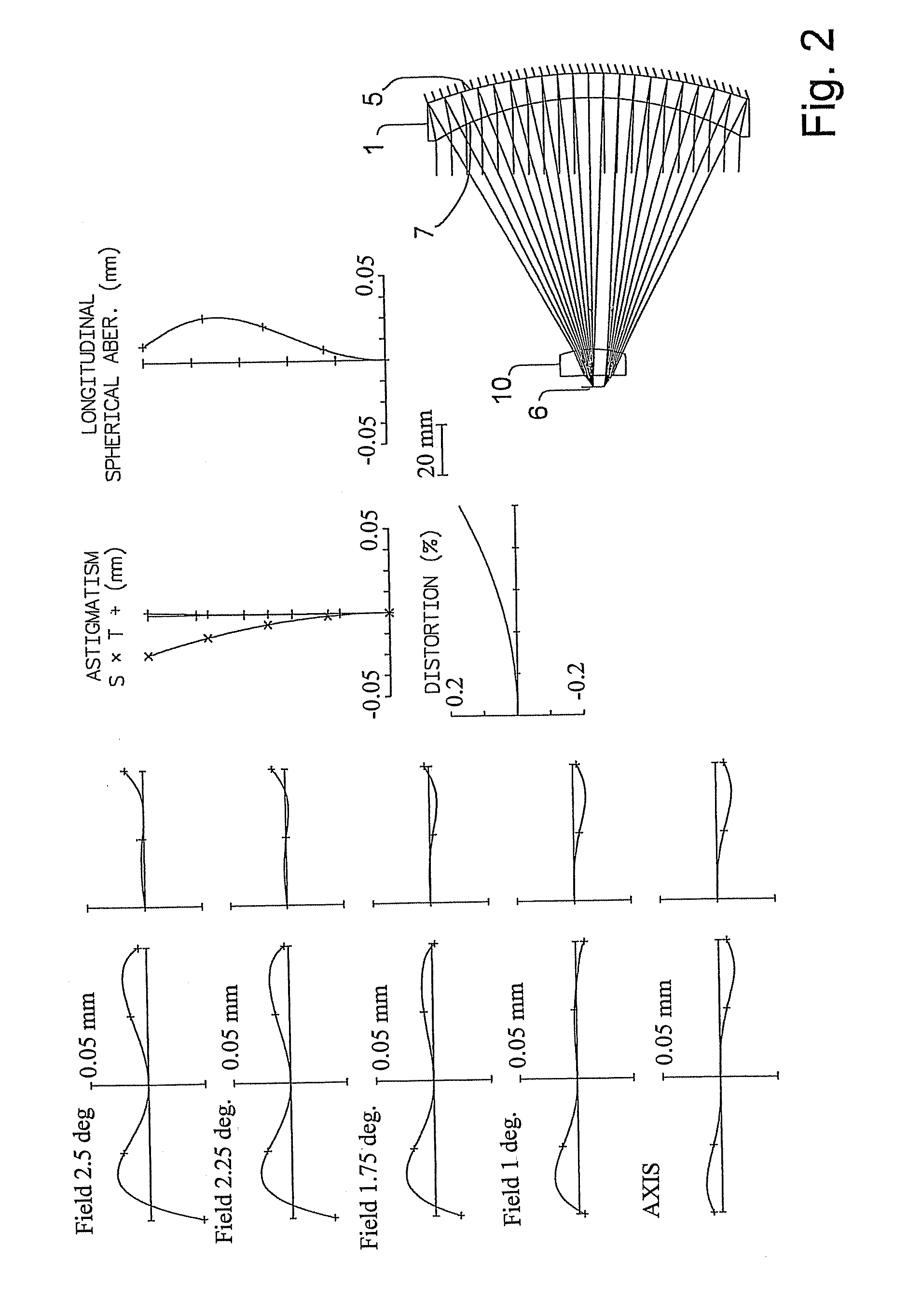
[0034]The correction diagrams show the ratios for the ×0.4, ×0.7 and ×0.9 image height in addition to the transverse aberration on the optical axis and at the image edge. As regards the assessment of quality, it is immaterial whether or not the ray tracing is carried out from the aiming mark toward infinity or, in reverse, from infinity toward the image plane. The ray direction is reversible and merely causes a mirroring of the curve shapes at the axes or a sign reversal. For purposes of a clearer depiction, the beam path for the image center is shown in the upper part of the graphic depiction of the beam path and the path for the outermost edge point is shown in the lower part. In real devices, usually only one side of the optics is provided.

[0035]Light sources emitting in the red region, chiefly light-emitting diodes, are often used as aiming marks. The wavelength region is relatively narrow-band. Therefore, the system is evaluated exclusively monochromatically.

[0036]Aside from th...


PUM


Abstract

The invention is directed to a coaxially arranged, off-axis optical system for a sighting device or aiming device. It is the object of the invention to provide a possibility for constructing an optical system in such a way that the typical disadvantage with respect to the tightness of a sighting device in an open-type construction is overcome and a good flattening of the image field is achieved in addition to the high optical imaging quality of the aiming mark. According to the invention, by means of a coaxially arranged, off-axis optical system for a sighting device or aiming device comprising a lens group, wherein the lens facing the target object is constructed as a converging meniscus and the lens facing the eye is constructed as a diverging meniscus, with a dichroic reflector and an embodiment for the aiming mark, the above-stated object is met in that a correction lens with positive refractive power is arranged at a distance of less than 0.2-times the focal length relative to the aiming mark and acts exclusively in the beam path of the aiming mark, and in that the correction lens is inserted into the housing by positive locking and is sealed so that the housing with the aiming mark, with the associated mechanism and with the electronics in the interior is sealed relative to the environment.

Description

FIELD OF THE INVENTION[0001]The invention is directed to a coaxially arranged, off-axis optical system for a sighting device or aiming device.BACKGROUND OF THE INVENTION[0002]Reflex sights work on the principle that an aiming mark, usually a dot, is imaged at infinity by a concave mirror. Owing to the fact that this concave mirror is constructed as a semitransparent mirror, it simultaneously opens up the view to the target. The target and aiming mark must be acquired without accommodation of the eye through an appropriate design of the general system.[0003]Typically, these devices are virtually non-magnifying aiming devices which are outfitted with a virtual luminous mark imaged at infinity. Therefore, the names red dot sight or collimator sight are also commonly used for these devices.[0004]A substantial advantage of reflex sights over telescopic sights consists in that there is no system-dependent predetermined distance between the sight and the eye for their use. This distance ca...

Claims


Application Information

Patent Timeline
Patent Type & Authority Patents(United States)
IPC IPC(8): G02B23/10G02B17/00F41G1/00
CPCG02B23/10G02B27/0025
Inventor KOEHLER, ALBRECHT
Owner NOBLEX E OPTICS GMBH
Why Eureka
Try Eureka